Stainless steel surface engineering
Stainless Steel Weld-Seam Finishing: Geometry, Heat Tint, Inspection, and RFQ Control
In this guide
TL;DR
Weld-seam finishing is not one operation. It can include removal of spatter and sharp projections, blending or retaining the weld profile, matching a directional or polished finish, removing heat tint and oxide, cleaning residues, and restoring a suitable...
1. What weld-seam finishing includes
A completed stainless weld presents at least four separate questions. First, is the joint structurally sound and within the specified imperfection limits? Second, does its profile meet functional geometry for fatigue, flow, sealing, or fit? Third, has heat-generated oxide and contamination been removed to the required corrosion condition? Fourth, does the visible texture match adjacent surfaces? A process can succeed on one question and fail another [9][10][11][12].
Weld dressing changes geometry by removing spatter, excess reinforcement, sharp transitions, or surface irregularities. Grinding, flap abrasives, files, belts, and nonwoven finishing media are common tool classes. The exact route must preserve required weld throat, wall thickness, edge geometry, and parent material. Dressing cannot create missing penetration, fuse a lack-of-fusion defect, or make a crack acceptable [10][11][12].
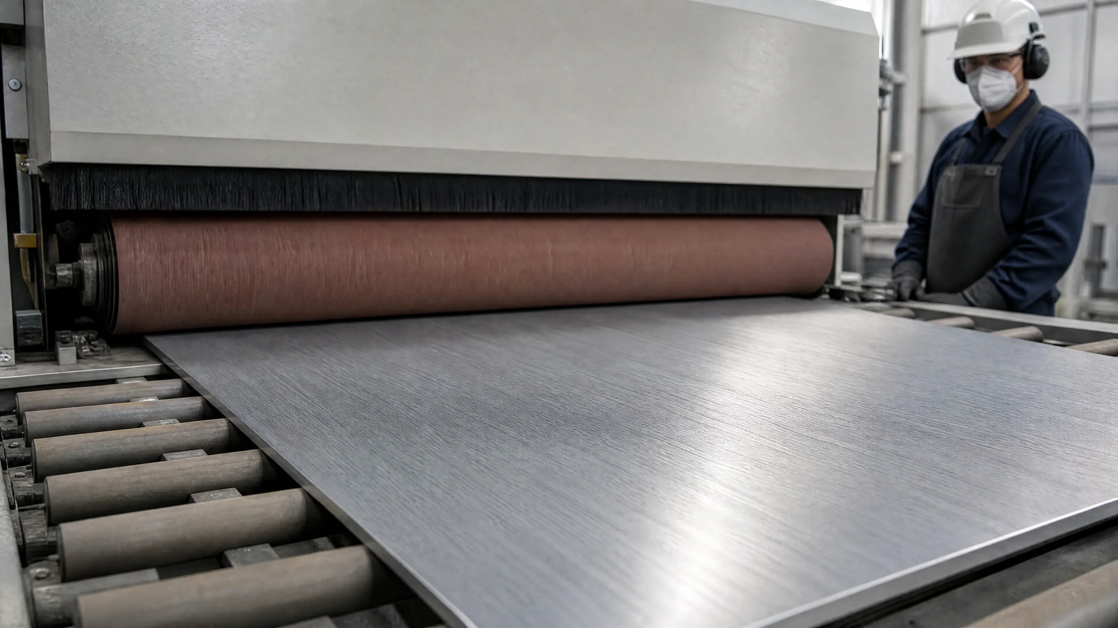
Finish blending makes the treated region visually and topographically compatible with surrounding material. On a directional No. 4-type surface, that means controlling abrasive sequence, line direction, overlap, and blending width. On a nondirectional or polished surface, it may require a different sequence. “Flush” describes geometry; “match surrounding finish” describes appearance. They are not interchangeable [4][9].
Heat-tint removal and post-weld cleaning address oxide, altered near-surface chemistry, and shop contamination. Mechanical abrasion, brushing, pickling, electrolytic cleaning, and laser cleaning remove or modify the surface through different mechanisms. ASTM A380/A380M provides the broad cleaning, descaling, and passivation practice framework for stainless parts and systems [9]. This article does not reproduce protected chemical recipes or acceptance tables.
Passivation may follow cleaning when required by the project. It treats an already clean surface and should not be expected to remove thick weld scale or repair geometry. A finished seam may therefore need structural inspection, mechanical dressing, chemical oxide removal, final blending, cleaning, and passivation as separately controlled stages [9].
2. Why welding changes the stainless surface
Heat tint and oxide formation
Welding heats the metal and surrounding surface in air or shielding conditions that vary along the joint. Colored oxides form as the surface reaches different thermal histories. Color is influenced by oxide thickness, composition, viewing, and lighting; it is not a universal thermometer. Westin, Olsson, and Hertzman studied oxide formation on lean-duplex stainless welds, while Kawano and co-workers investigated local electrochemical behavior in heat-tinted zones [2][3].
The oxide and the metal immediately beneath it can differ chemically from unaffected stainless. Chromium participates in oxide formation, and the resulting near-surface state may have lower localized-corrosion resistance than the properly cleaned parent surface. Trigwell and Selvaduray examined how welding affected the passive oxide film of electropolished 316L, demonstrating that a premium starting finish does not prevent weld heat from changing the surface [4].
Heat-tint color alone does not fully define corrosion performance. Different alloys and weld conditions can produce different surface and electrochemical responses, so a visible shade should not be treated as a universal corrosion rating. In severe service, specify an objective cleaning and verification route rather than accepting or rejecting solely by a generic color chart. A color reference can remain useful as a production control if it is tied to the exact alloy, weld process, lighting, and project criterion [1][3][5].
Heat-affected zone and weld metal
Below the oxide, the weld thermal cycle creates a fusion zone and heat-affected zone (HAZ). Weld metal composition, phase balance, grain structure, precipitates, segregation, residual stress, and the width of thermally affected material depend on grade, filler, heat input, shielding, joint design, and cooling. Ma and co-workers studied microstructure and corrosion behavior in the HAZ of a 308L-316L weld joint [8]. Their findings support alloy- and procedure-specific evaluation, not a universal post-weld grinding depth.
Duplex stainless steels require particular attention to weld thermal history because their properties depend on an appropriate phase balance and absence of harmful changes. Wickström, Hinds, and Turnbull studied the influence of weld preparation and heat tint on sulfide stress-corrosion cracking of duplex stainless steel [5]. Surface finishing cannot reverse an unsuitable weld microstructure; welding-procedure qualification and material control remain upstream requirements.
Surface geometry and stress concentration
Weld toes, reinforcement, undercut, mismatch, stop-start regions, crater shape, and grinding marks can influence flow, cleanability, fatigue, and appearance. A smooth transition may be desirable, but indiscriminate grinding can reduce section thickness or leave transverse scratches that create their own stress concentration. The drawing should state which profile is required and how much parent-metal removal is allowed [11][12].
If fatigue is critical, cosmetic smoothness is not enough. The design category, weld quality, toe geometry, residual stress, inspection, and loading spectrum matter. A finishing supplier should not be asked to infer a structural fatigue requirement from a photograph. Engineering must define the joint and post-weld treatment before production [11][12].
3. How the main finishing routes work
Mechanical grinding and blending
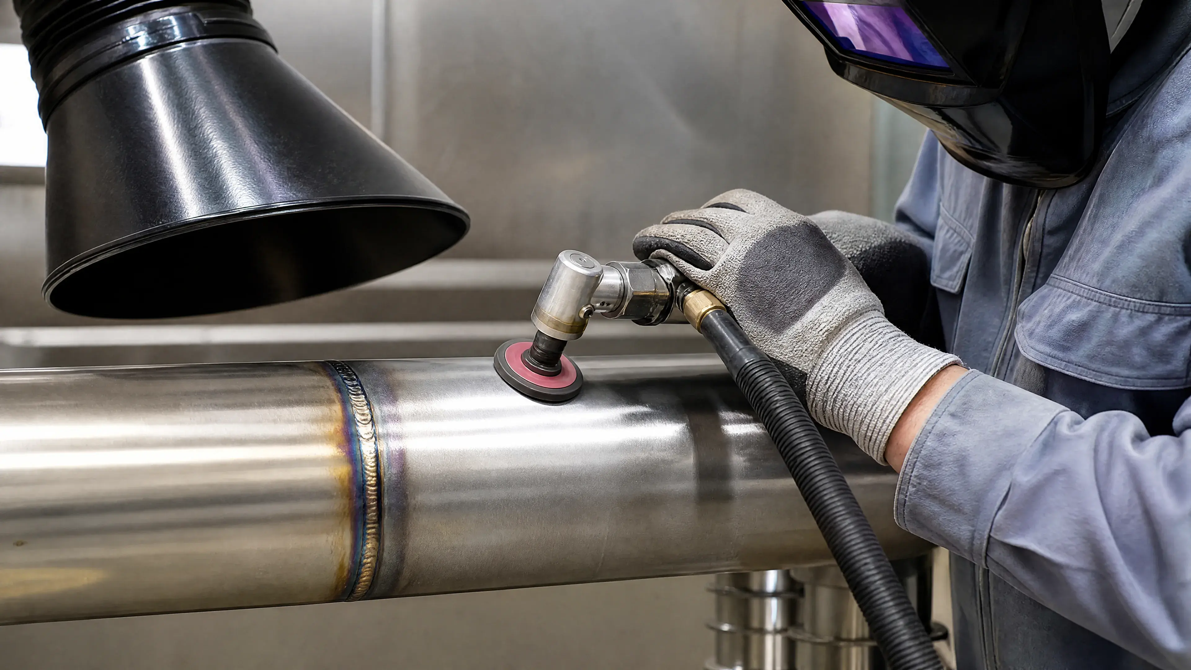
Abrasive grains cut the weld and adjacent surface. Coarse products remove reinforcement and large irregularities; progressively finer products reduce the preceding scratch pattern and create the final texture. Tool stiffness, abrasive size, pressure, speed, angle, dwell, and operator path control removal. Heat generated during aggressive grinding can discolor or distort thin stainless, while excessive pressure can gouge the parent surface [1][9].
Mechanical work is best at geometry correction and texture matching. It can also remove visible oxide if enough material is cut, but apparent color removal does not prove that the entire chemically affected surface is gone. In a study of heat-tinted 2507 duplex TIG welds, Fuertes and co-workers found that the tested mechanical brushing and brushing-plus-polishing routes did not eliminate the measured anodic activity as effectively as brushing followed by pickling [1]. This result belongs to that alloy, weld, and test program; it should prompt qualification, not a blanket ban on mechanical cleaning.
Abrasive tools must be dedicated to stainless where foreign-iron contamination matters. Embedded carbon steel or dirty media can create later staining. Each abrasive step should remove the prior step’s scratches without widening the blend zone unnecessarily. A defined direction and endpoint reduce the risk of a visually acceptable centerline surrounded by a large mismatched halo [9].
Chemical pickling and passivation
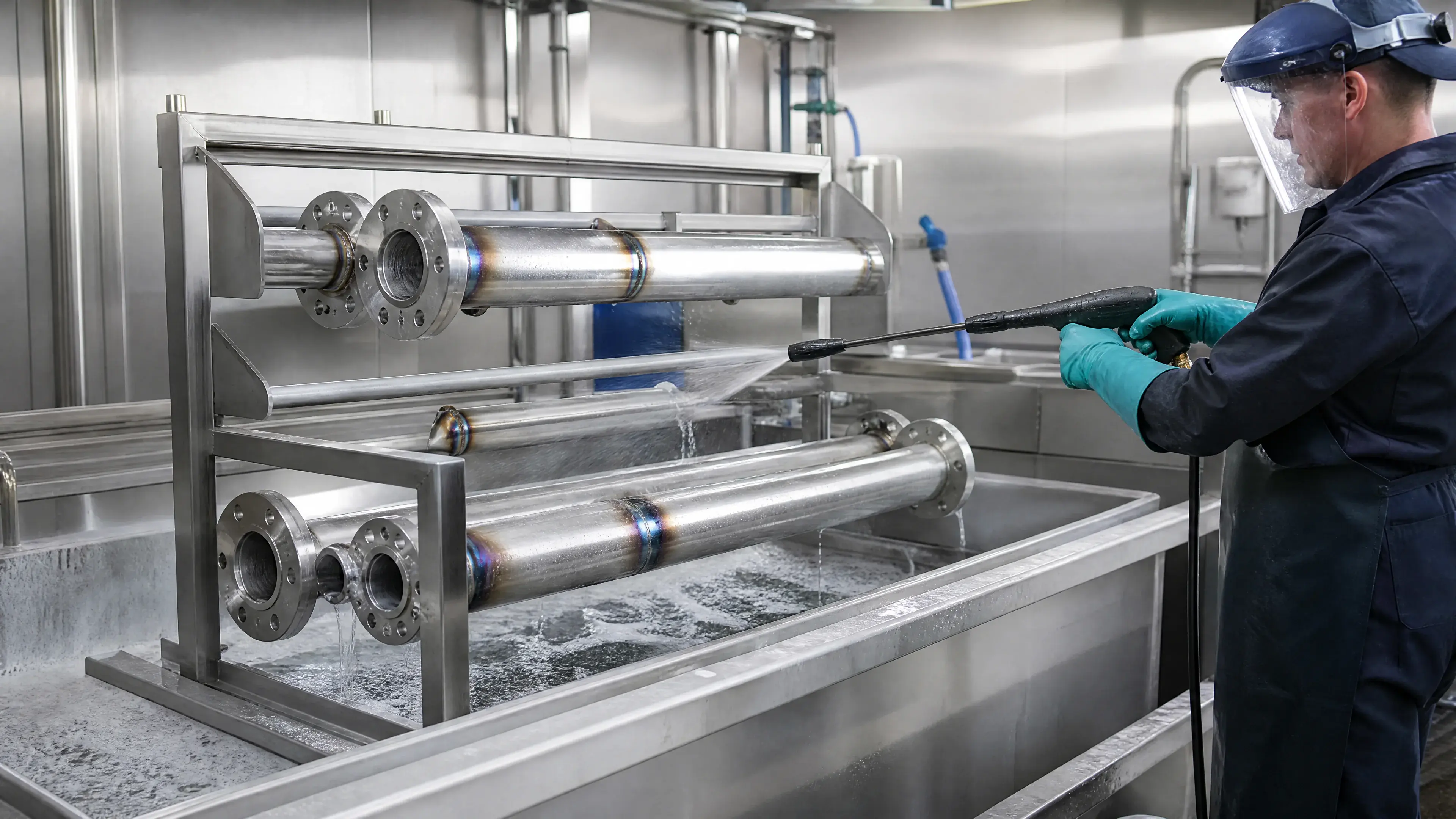
Pickling dissolves oxide and some underlying material. It can treat complex surface microtopography more completely than a brush that touches only exposed peaks, but it also introduces chemical compatibility, masking, drainage, residue, dimensional, and safety controls. Local application and immersion are different delivery methods and may leave different boundaries or appearance [1][9].
The 2507 study by Fuertes and co-workers found brushing followed by pickling most effective among its investigated cleaning routes, producing a passive response in the reported SVET measurements and a higher measured critical pitting temperature [1]. Those comparative findings support thorough oxide removal on that system. They do not supply a universal acid, exposure time, temperature, or acceptance value for 304, 316L, or every duplex grade.
After pickling, complete rinsing and residue removal are essential, especially at lap joints, threads, tube roots, and crevices. Passivation may follow under the approved specification. ASTM A380/A380M treats cleaning, descaling, and passivation as related but distinct functions, reinforcing the need to document the full sequence [9].
Electrolytic weld cleaning
Electrolytic cleaning applies current through an electrolyte and a local tool to remove tint or modify the surface near the weld. Access can be convenient for fabricated assemblies, but the process still needs compatible chemistry, controlled contact, complete coverage, rinsing, and residue verification. Tool marks or halos can matter on architectural finishes [9].
An RFQ should distinguish electrolytic weld cleaning from full-part electropolishing. Local current density, tool dwell, electrolyte replenishment, and contact area differ from immersion electropolishing. Neither label proves a specific passive condition without a qualified procedure and agreed verification [4][9].
Laser cleaning
Pulsed laser energy can ablate or disrupt weld oxide without conventional abrasive contact. Kumar and co-workers studied laser-assisted removal of GTAW heat tint and compared morphology, roughness, and pitting behavior with conventional cleaning routes [6]. Guo, Martukanitz, and DebRoy studied laser-assisted cleaning of oxide films on SUS409 stainless steel [7]. These studies establish technical feasibility on their test systems.
Laser process windows depend on wavelength, pulse duration and shape, fluence, overlap, focus, scan speed, oxide, and substrate. Kumar and co-workers reported a threshold behavior that varied with pulse duration [6]. That finding should not be converted into a universal machine setting. Overexposure can alter roughness or surface condition, while incomplete overlap can leave oxide. Production use needs representative qualification and laser-safety controls.
4. Variables that control the result
Alloy, weld process, and shielding
The cited studies address different systems: 2507, lean duplex, electropolished 316L, 22Cr duplex, SUS409, and a 308L-316L joint [1][2][4][5][7][8]. They do not establish one shared oxide, corrosion, or weld-metallurgy response. The RFQ should state base grade, filler, product thickness, weld process, shielding and backing method, and whether the root or face is treated. A procedure proven on an austenitic sheet should not be transferred to duplex pipe without review.
Gas coverage, purge quality, torch angle, travel speed, heat input, interpass control, and joint fit affect tint and bead condition before finishing. In the cited 22Cr duplex study, backing-gas oxygen and pipe alignment were among the variables associated with undesirable heat-tint and stress-concentration effects [5]. The best finishing strategy begins with a repeatable weld that minimizes unnecessary oxide and excess reinforcement. Post-weld processing should not be used as permission for uncontrolled welding [4][5][8].
Required weld profile
A weld may remain as-welded, have spatter and sharp projections removed, be blended at the toes, be ground flush, or be polished into a low-visibility transition. Each level removes a different amount of material and carries different inspection risk. The drawing should show treated side, final contour, minimum thickness, undercut rule, edge radius, and prohibited reduction [10][11][12].
Grinding flush before required visual or volumetric inspection can obscure surface indications or change the geometry used for acceptance. Define inspection hold points. Some joints require inspection as welded, after root work, after dressing, and after final cleaning. ISO 17635 provides the general NDT framework, ISO 17637 addresses visual testing, and ISO 5817 supplies imperfection quality levels when invoked by the design [10][11][12].
Starting finish and appearance zone
Mill 2B, brushed, bead-blasted, mechanically polished, and electropolished surfaces require different blend strategies. A coarse grinder used near a finished face can create irreversible texture change beyond the weld. The RFQ should identify visible faces, grain direction, approved blend width, and whether a physical sample governs [4][9].
On directional finishes, every final stroke should follow the intended lay. Cross-grain scratches that look minor head-on can become obvious under grazing light. On mirror-like surfaces, geometric waviness often remains even after fine scratches disappear. Color, gloss, lay, and contour need separate acceptance language [4][9].
Tool, abrasive, and contamination control
Variables include abrasive mineral, grit or grade, product format, backing stiffness, wheel diameter, condition, speed, pressure, path, and lubricant. “Polish” without a sequence is not reproducible. Process documents should identify approved tool families and prevent use after contact with carbon steel or unknown alloys [1][9].
Grinding debris can lodge in corners or internal passages. Nonwoven media can smear residue; compounds can remain in pores and seams. Cleaning after mechanical work must remove abrasive, metallic particles, oil, and compound. If elemental contamination matters, specify a verified cleanliness method rather than relying on dedicated-tool labels [9].
Chemical coverage and rinsing
Local pickling products can dry, run, collect at a lower edge, or seep beneath masking. Variations in oxide thickness make the visible endpoint nonuniform. Time, temperature, chemistry condition, applied thickness, surface orientation, and prior abrasion all affect reaction [1][9]. The processor must use a grade-appropriate qualified procedure and protect dissimilar materials.
Rinsing is challenging in hollow fabrications and hygienic tubing. Residue trapped behind a backing ring, in a socket, or beneath overlap can create later contamination or corrosion. Drain and vent design, rinse access, water quality, neutralization if specified, and final drying must be included in process planning [9].
5. Performance benefits and hard limits
Corrosion condition
Thorough removal of weld oxide and contamination can improve localized-corrosion behavior relative to an untreated heat-tinted surface. That relationship is supported by studies using electrochemical mapping, pitting tests, and passive-film analysis on specific stainless welds [1][3][4][6]. Improvement must be framed against the studied starting condition and test, not as proof of immunity in service.
Finishing cannot change the bulk grade, eliminate a poor crevice design, correct sensitization or phase imbalance, or protect a later carbon-steel-contaminated surface. If service exceeds the alloy’s chloride, temperature, stress, or chemical capability, a bright seam can still corrode. Alloy selection, welding, geometry, cleaning, and service control work together [1][5][8][9].
Cleanability and roughness
Blending can reduce abrupt bead features and surface peaks, but functional acceptance is not established by appearance alone. Profile roughness, pits, undercut, overlap, crevices, and accessibility all matter. A single Ra value on adjacent sheet cannot qualify the weld root or transition [1][3][4].
If roughness matters, specify parameter, filter/evaluation conditions, measurement direction, and exact zones: parent metal, weld crown, toe, blended region, and root. Curved or internal surfaces may need replica or specialized methods. State how isolated pits, scratches, or pores are accepted in addition to the average [3][4][9].
Appearance
A skilled blend can make a weld less conspicuous, but a perfectly invisible repair cannot be guaranteed across different heats, weld filler, cold work, lighting, and thermal history. Chemical treatment can leave a pale halo; grinding can widen the directional blend; polishing can reveal waviness. A signed sample made from production material and weld process is the safest appearance reference [1][4][9].
Cosmetic acceptance should be separated from corrosion acceptance. Residual color may fail a visual requirement even if a specified corrosion test passes; a uniform silver surface may fail cleanliness or passive-surface verification. Writing two criteria prevents subjective appearance from substituting for engineering evidence [1][3][9].
Structural integrity
No finishing method repairs internal porosity, lack of penetration, lack of fusion, cracking, or incorrect filler. Grinding may expose a defect, remove evidence, or reduce effective section. Any indication found during finishing should stop the affected work and trigger the documented weld-repair procedure, not continued polishing [10][11][12].
Repaired welds need the required reinspection and complete post-weld finishing sequence again. The repair area may have a different thermal and cosmetic history, so the drawing or quality plan should define whether repaired visible zones require renewed sample approval [10][11][12].
6. Grade and component compatibility
Austenitic 304/304L and 316/316L are common fabricated grades, and the cited literature includes electropolished 316L and a 308L-316L joint [4][8]. Their finishing procedure still depends on thickness, weld, service, and starting finish. Low-carbon designations do not make heat-tint removal or contamination control unnecessary.
Duplex and super-duplex stainless require grade-specific welding and cleaning qualification. Separate studies on lean-duplex weld oxide formation, 2507 tint cleaning, and 22Cr duplex pitting and sulfide stress-corrosion cracking show why grade, welding conditions, surface preparation, and oxide state must be evaluated together [1][2][5]. Aggressive grinding also risks local heating and dimensional change.
Ferritic stainless can form different weld oxides and may have different grain-growth or embrittlement concerns. The SUS409 laser-cleaning study demonstrates one ferritic case, not blanket compatibility [7]. Martensitic and precipitation-hardening grades can have hardness and heat-treatment requirements that constrain welding and rework.
Thin sheet can distort or be gouged during dressing. Heavy plate and multi-pass welds create broader thermal histories. Tubing adds root access and purge considerations. Mixed-metal assemblies, plated hardware, sealants, and polymers can be damaged by chemical or thermal cleaning and must be identified before treatment [7][9].
7. Inspection and acceptance
Create a hold-point sequence before welding begins. Material identity, joint preparation, fit-up, welding procedure, consumables, shielding, and welder qualification belong upstream. Required in-process and final NDT should occur at stages where finishing has not hidden relevant evidence. ISO 17635 gives general NDT selection rules, and ISO 17637 provides the visual-testing framework [10][12].
Use the drawing or governing fabrication code to select imperfection limits. ISO 5817 provides quality levels when explicitly invoked, but its protected tables should be applied by qualified personnel under the purchased edition [11]. This article does not assign a default quality level or reproduce imperfection dimensions.
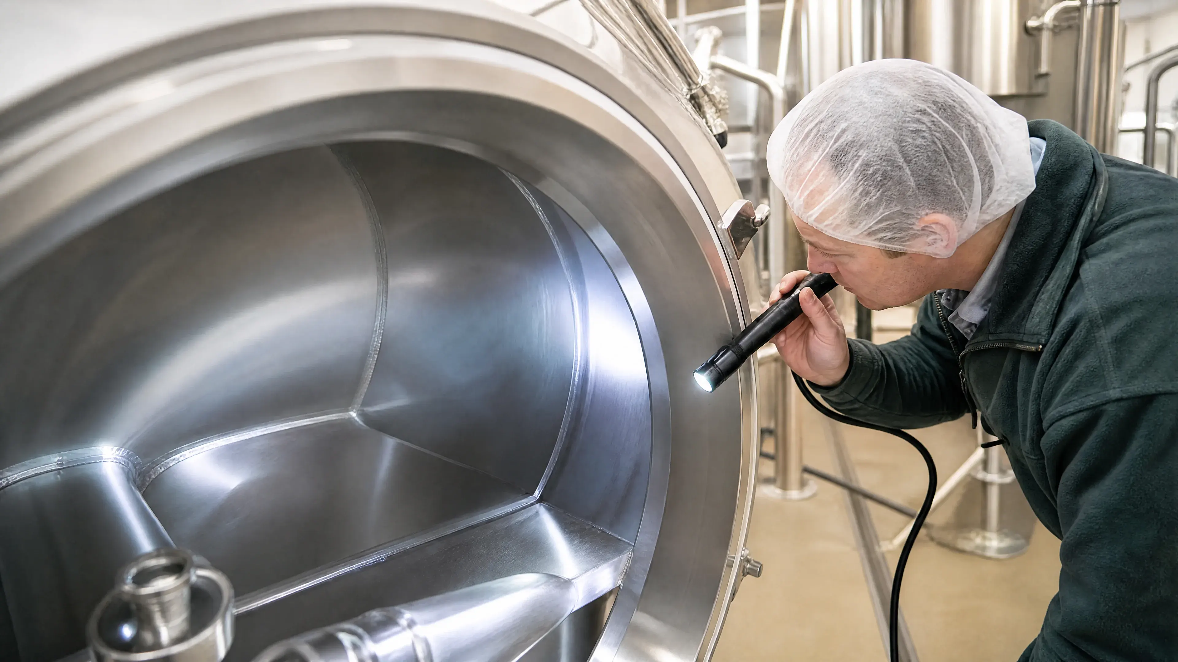
After structural acceptance and authorized dressing, inspect final contour, minimum thickness, undercut or transition, edge condition, and roughness at the specified locations. Tools can include gauges, profilometry, wall-thickness measurement, borescopes, replicas, and physical comparison samples. The method must fit the geometry and resolution required [10][11][12].
Post-cleaning visual inspection should use controlled light to check residual tint, scale, streaks, chemical halos, scratches, embedded particles, and incomplete root coverage. It cannot alone establish passive-film chemistry. If passivation, contamination, or corrosion verification is required, name the method, acceptance criterion, lot, and failed-lot disposition under ASTM A380/A380M or the project specification [9].
Traceability should link material, weld map, welding procedure, filler lot where required, welder, inspection reports, repair history, finishing procedure, abrasive or chemical route, processing lot, passivation record, and final acceptance. A certificate stating only “welds polished” does not identify what was inspected or achieved [9][10][12].
8. Practical workflow
- Define weld and finish requirements. Confirm joint design, structural quality level, service, profile, appearance, heat-tint limit, roughness, post-weld chemistry, and documentation.
- Approve representative samples. Use production grade, thickness, weld process, filler, shielding, and starting finish for appearance or roughness-critical work.
- Inspect fit-up and welding controls. Verify material, preparation, purge/shielding, procedure, and access before the joint becomes closed.
- Perform required weld inspection. Complete visual and other NDT at the specified hold points before dressing can conceal relevant indications [10][11][12].
- Correct weld defects through the approved repair route. Do not grind structural imperfections into cosmetic acceptance; reinspect repaired joints.
- Dress geometry. Remove only authorized reinforcement, spatter, sharp projections, and transition material while protecting thickness and adjacent finish.
- Blend the visible texture. Progress through the qualified abrasive sequence, maintain grain direction, control blend width, and clean debris.
- Remove heat tint and oxide. Apply the qualified mechanical, chemical, electrolytic, laser, or combined route for the actual grade and weld condition [1][6][7][9].
- Rinse, passivate, dry, and protect as specified. Prevent retained chemistry and post-process iron contamination.
- Final inspect and release. Verify contour, dimensions, roughness, appearance, cleanliness, passive/corrosion requirement, records, and packaging.
Sequence can vary. For example, preliminary abrasion may precede pickling, and a final light blend may follow chemical treatment on a visible face. Any reordered sequence must be qualified because later abrasion can disturb a previously passivated surface and chemical treatment can change a finished appearance [1][9].
9. Alternatives and neighboring processes
Improved welding control is the first alternative to heavy finishing. Better fit-up, heat input, shielding, purge, bead placement, and stop-start planning can reduce tint and excess reinforcement. The 22Cr duplex study specifically identifies backing-gas oxygen and pipe alignment as important controls in its test system [5]. Prevention preserves thickness and shortens downstream work [4][5][8].
As-welded acceptance with chemical cleaning can be appropriate when the bead profile is functional and only oxide/passive condition needs correction. It avoids unnecessary geometric removal. The drawing must still define acceptable bead and imperfection limits [9][10][11].
Full electropolishing can be evaluated as a separate whole-part route after suitable weld preparation. Because welding alters the previously electropolished 316L passive surface and electropolishing changes dimensions and appearance, the complete sequence needs its own qualification [4][9].
Localized mechanical blending only may suit cosmetic indoor work where the qualified corrosion requirement permits it. The 2507 study warns that visual removal by mechanical means did not eliminate electrochemical activity in that specific system [1]. Use representative testing rather than assuming the same outcome for every grade.
Laser cleaning offers noncontact oxide removal and automation potential but needs equipment-specific qualification, coverage control, surface verification, and safety infrastructure [6][7]. It is an alternative cleaning mechanism, not a weld-defect repair method.
Coating over the weld does not eliminate the need for structural acceptance, appropriate oxide removal, adhesion preparation, and crevice control. An opaque layer can conceal an untreated problem, so inspection and qualified pretreatment must occur first [9][10].
10. Typical applications
Hygienic process tubing and vessels
These systems may require smooth internal transitions, controlled root geometry, low residue, and verified cleaning. Outside appearance does not establish internal root condition. Weld maps, borescope access, roughness sites, chemical rinse, and passivation should be planned before assembly closure [9][10][12].
Architectural rails, panels, and visible fabrications
Appearance and corrosion both matter. Grain direction, blend width, lighting, corner continuity, filler color, and chemical halo need physical samples. Structural inspection must precede the work that makes a seam visually disappear [10][11].
Chemical and marine equipment
Chloride-, acid-, or sulfide-bearing service can make weld condition and heat-tinted zones critical. Studies on post-weld cleaning of heat-tinted 2507 and on pitting and sulfide stress-corrosion cracking around 22Cr duplex welds reinforce the need for grade-specific weld control and qualified post-weld cleaning [1][5]. Maximum brightness is not the engineering endpoint.
Electropolished and high-purity assemblies
Welding disrupts the previously electropolished passive surface, as demonstrated for 316L [4]. The fabrication plan should state whether seams are dressed before whole-part electropolishing, locally cleaned, or treated through another validated route. Final roughness, cleanliness, and passivation evidence must cover the weld zones, not only untouched parent material.
11. RFQ checklist
- Base and filler grades, product form, thickness, joint design, weld process, shielding/backing, welding specification, and traceability.
- Governing fabrication code, ISO 5817 quality level if applicable, NDT methods, acceptance, inspector qualification, and hold points [10][11][12].
- Treated side and zone: face, root, both sides, toes only, full visible panel, or internal wetted surface.
- Required final weld profile: as-welded cleaned, spatter removed, toe blended, reinforcement limit, flush, or seamless visual transition.
- Minimum remaining thickness, permitted parent-metal removal, edge radius, wall tolerance, and dimensions before/after finishing.
- Starting finish, final roughness parameter and method, grain direction, blend-width limit, color/gloss, and approved physical sample.
- Heat-tint and oxide acceptance by grade and zone; qualified removal route; prohibited chemicals or abrasives.
- Dedicated-tool, media, contamination, residue, rinse-water, drying, and post-treatment handling requirements.
- Pickling/passivation specification and edition, verification method, sampling, and failed-lot disposition [9].
- Access, drain, vent, masking, dissimilar-material, internal-passage, and media/chemical recovery constraints.
- Weld repair procedure, reinspection, refinish requirements, visible-repair approval, and maximum repair allowance.
- Required weld map, procedure records, NDT reports, repair log, finishing/passivation certificate, first article, and packaging.
12. Frequently asked questions
Is removing the heat-tint color enough to restore corrosion resistance?
Not by assumption. Visible color can disappear while chemically altered or electrochemically active surface remains. In one 2507 duplex study, tested mechanical routes were less effective than brushing followed by pickling at eliminating measured activity [1]. Use a qualified grade-specific route and specified verification.
Can grinding make a defective weld acceptable?
No. Grinding can shape an already acceptable weld or expose an indication; it cannot repair cracking, lack of fusion, insufficient penetration, or internal porosity. Structural acceptance and required NDT must follow the drawing and governing standard, with defects repaired by an approved welding procedure [10][11][12].
Must every stainless weld be ground flush?
No. Flush grinding removes material and may be unnecessary or harmful. Some applications retain an acceptable bead and require only oxide removal and cleaning; others need a blended profile for flow, fatigue, appearance, or fit. The drawing should define the functional endpoint [10][11][12].
Is laser cleaning automatically better than pickling or brushing?
No. Published studies demonstrate that controlled laser parameters can remove oxide and improve measured surface behavior in specific systems [6][7]. Equipment, oxide, alloy, geometry, overlap, roughness, access, and verification determine suitability. It remains a qualified alternative, not a universal replacement.
References
- Fuertes, N., Bengtsson, V., Pettersson, R., & Rohwerder, M. “Use of SVET to evaluate corrosion resistance of heat tinted stainless steel welds and effect of post-weld cleaning.” Materials and Corrosion (2016). https://doi.org/10.1002/maco.201609048. Access note: DOI metadata and abstract reviewed; claims are limited to the reported 2507 duplex TIG system and compared cleaning routes.
- Westin, E. M., Olsson, C.-O. A., & Hertzman, S. “Weld oxide formation on lean duplex stainless steel.” Corrosion Science (2008). https://doi.org/10.1016/j.corsci.2008.06.024. Access note: DOI and bibliographic metadata verified; no abstract or full text was available during this audit, so use is limited to the study scope stated by the title.
- Kawano, T., Ishii, T., Kajiyama, H., Kimura, M., & Fushimi, K. “Microelectrochemistry at Heat-tinted Zone of Stainless Steel Weldment.” Zairyo-to-Kankyo (2015). https://doi.org/10.3323/jcorr.64.552. Access note: DOI metadata and indexed abstract verified; use is limited to the local electrochemical relevance of heat-tinted zones.
- Trigwell, S., & Selvaduray, G. “Effects of welding on the passive oxide film of electropolished 316L stainless steel.” Journal of Materials Processing Technology (2005). https://doi.org/10.1016/j.jmatprotec.2004.07.091. Access note: DOI metadata and indexed abstract verified; no unreviewed numerical surface-composition value is used.
- Wickström, L., Hinds, G., & Turnbull, A. “Influence of Weld Preparation Procedure and Heat Tinting on Sulfide Stress Corrosion Cracking of Duplex Stainless Steel.” CORROSION (2015). https://doi.org/10.5006/1645. Access note: DOI metadata and public indexed abstract reviewed; use is limited to the 22Cr duplex surface-preparation, backing-gas oxygen, pitting, and sulfide stress-corrosion results stated in that abstract.
- Kumar, A., Gumma, S., Roychowdhury, S., Kain, V., Bhatt, R. B., Nilaya, J. P., & Biswas, D. J. “Laser-assisted removal of weld heat tints from stainless steel surface.” Journal of Laser Applications (2021). https://doi.org/10.2351/7.0000561. Access note: DOI metadata and abstract reviewed; pulse-specific thresholds and numerical performance are not generalized.
- Guo, H., Martukanitz, R. P., & DebRoy, T. “Laser assisted cleaning of oxide films on SUS409 stainless steel.” Journal of Laser Applications (2004). https://doi.org/10.2351/1.1809639. Access note: DOI metadata and indexed abstract verified; use is limited to feasibility on the stated ferritic stainless system.
- Ma, C., Peng, Q., Mei, J., Han, E.-H., & Ke, W. “Microstructure and corrosion behavior of the heat affected zone of a stainless steel 308L-316L weld joint.” Journal of Materials Science & Technology (2018). https://doi.org/10.1016/j.jmst.2017.12.016. Access note: DOI metadata and indexed abstract verified; no microstructural or corrosion value is transferred beyond the studied joint.
- ASTM International. ASTM A380/A380M-25, Standard Practice for Cleaning, Descaling, and Passivation of Stainless Steel Parts, Equipment, and Systems. https://doi.org/10.1520/A0380_A0380M-25. Access note: official DOI and current-edition metadata verified; protected recipes, tables, clauses, and acceptance values were not accessed or reproduced.
- International Organization for Standardization. ISO 17637:2016, Non-destructive testing of welds — Visual testing of fusion-welded joints, Edition 2, published 2016-12. https://www.iso.org/standard/67259.html. Access note: title, edition, publication date, and active “Published” status verified in the official ISO catalogue; protected standard text was not accessed or reproduced.
- International Organization for Standardization. ISO 5817:2023, Welding — Fusion-welded joints in steel, nickel, titanium and their alloys (beam welding excluded) — Quality levels for imperfections, Edition 4, published 2023-02. https://www.iso.org/standard/80209.html. Access note: title, edition, publication date, and active “Published” status verified in the official ISO catalogue; protected tables and clause text were not accessed or reproduced.
- International Organization for Standardization. ISO 17635:2025, Non-destructive testing of welds — General rules for metallic materials, Edition 4, published 2025-04. https://www.iso.org/standard/85705.html. Access note: title, edition, publication date, and active “Published” status verified in the official ISO catalogue; protected standard text was not accessed or reproduced.
Continue the specification
Related surface-finish guides
Specify before production
Need a finish quoted against a drawing or control sample?
Send the material grade, product form, finish requirement, inspection method and quantity. We will identify the unresolved specification points before quoting.
Discuss the requirement