Stainless steel surface engineering
Food-Grade Stainless Steel Surface Finish: Engineering and Procurement Requirements
In this guide
TL;DR
“Food-grade finish” is not one universal stainless-steel grade, one polishing number, or one roughness value. A compliant equipment surface is the result of several controlled layers: material identity and jurisdictional suitability; equipment geometry;...
1. What “food-grade surface finish” means
The phrase is a procurement shorthand, not a self-executing technical specification. A stainless sheet can conform to a material specification yet be fabricated into equipment with unacceptable joints, trapped volumes, damaged surfaces, or undocumented contact materials. Conversely, a finely polished surface does not make an unidentified alloy or noncompliant assembly suitable for a regulated application. Material compliance and equipment design are related but separate acceptance tracks [1][2][3][4].
Material compliance concerns the identity, composition, traceability, and suitability of every contact material for the intended jurisdiction and use. ASTM A240/A240M covers chemical and mechanical requirements for chromium and chromium-nickel stainless plate, sheet, and strip, but conformity to that material standard is not, by itself, a complete food-contact approval for a finished machine [1][3][8].
Equipment design compliance concerns geometry, joints, accessibility, drainage, assembly interfaces, and the condition of finished contact surfaces. ISO 14159 addresses hygiene requirements in machinery design, and the FDA Food Code includes model equipment provisions for multiuse food-contact surfaces and cleanability. The purchaser must identify which adopted law, code, customer standard, or equipment specification governs the project [3][4].
Surface-finish compliance concerns measurable topography and visible defects at defined locations. It may include a profile roughness limit, areal texture requirement, direction of lay, absence of unacceptable pits or folds, weld contour, and specified chemical treatment. The finish name alone—2B, brushed, mechanically polished, or electropolished—does not establish all of those attributes [5][6][7].
A defensible purchase specification connects the three tracks. It identifies a material, defines an equipment geometry, assigns a finish to each contact zone, and states how inspectors will verify the result. It also separates mandatory regulatory evidence from customer preferences such as a particular sheen or directional appearance [1][2][3][4].
2. How surface engineering affects acceptance
Surface topography
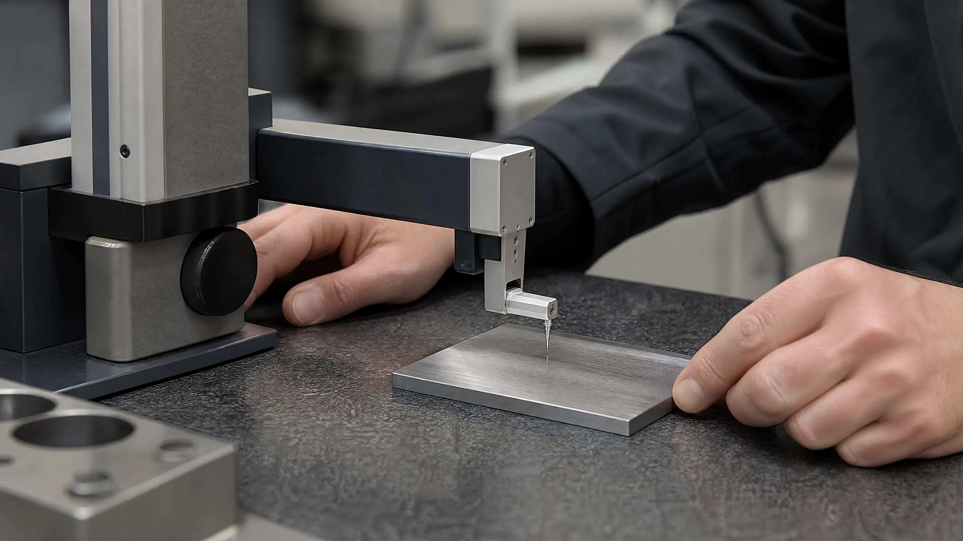
A manufactured surface contains roughness, waviness, lay, and isolated features at different scales. Profile instruments trace a line; areal instruments characterize an area. ISO 21920-2 defines profile surface-texture terms and parameters, ISO 21920-3 addresses profile specification operators, and ISO 25178-2 defines areal surface-texture terms and parameters [5][6][7]. Experimental metrology research also shows why instrument principle and analysis scale belong in the method definition rather than being treated as incidental [13][14].
Ra is the arithmetic mean deviation of a profile under specified evaluation conditions. It is widely used because it is compact and measurable, but one parameter cannot fully discriminate topographies produced by different processes or at different scales. A functional finish requirement may therefore need additional profile or areal parameters, a maximum individual defect rule, and visual or optical inspection [5][6][7][13][14].
The direction of measurement matters on a brushed surface. A trace across the lay and a trace along it can produce different results. Curved tube interiors, weld crowns, and transitions can also challenge stylus access and instrument setup. Research comparing stylus instruments and confocal microscopes reinforces the need to define and qualify the measurement principle for the surface and artifact used [5][6][7][13].
Defects and discontinuities
Average roughness does not authorize laps, cracks, embedded debris, open seams, sharp burrs, deep scratches, pits, or incomplete weld transitions. These features need separate definitions and inspection methods. Multiscale topography research shows that surfaces and process signatures can be distinguished differently depending on analysis scale, supporting a quality plan that combines numerical texture measurement with visual and geometric inspection [5][7][10][14].
Material defects must be distinguished from fabrication damage. Mill surface variation, inclusions, laminations, forming marks, grinding gouges, and weld imperfections have different causes and dispositions. Repeated polishing can enlarge a pit or reduce wall thickness without resolving its origin. The approved nonconformance process should decide repair, replacement, or engineering acceptance before further removal [8][11][12].
Weld geometry
Welds are part of the contact surface when they lie in the defined equipment zone. Required acceptance can include complete fusion under the governing fabrication specification, a controlled root and face contour, no prohibited crevice-forming geometry, a blended transition, and the same finish verification applied to adjacent material. ISO 17637 supplies a framework for visual testing of fusion-welded joints, while ISO 5817 defines weld-imperfection quality levels when invoked by the design [11][12].
Grinding a weld flush is not automatically required and is not automatically beneficial. It removes material and can conceal evidence if performed before the required inspection. The drawing should state whether the weld remains as welded, has projections removed, is toe-blended, is ground flush, or receives a specified polished contour. Structural acceptance and authorized repair precede final cosmetic blending [11][12].
Drainage and cleaning access
Surface finish cannot compensate for geometry that retains liquid or cannot be reached by the specified cleaning method. Equipment design must address slopes, low points, joints, corners, removable components, fastener interfaces, seals, tube branches, instrument connections, and access for inspection. ISO 14159 and the FDA Food Code provide official design context; project-specific dimensional criteria still need to be stated by the purchaser [3][4].
Drainage is a geometric property, not a polish grade. A smooth horizontal pocket can retain more liquid than a correctly oriented surface with a coarser but acceptable finish. Verification should examine actual installed orientation, deformation, weld pull, and support conditions, because a nominal drawing slope may not equal the final equipment slope [3][4].
Cleaning access likewise depends on the complete assembly. A polished surface behind a permanent overlap or inaccessible seal cannot be accepted through a coupon reading on an open flat plate. The design review should identify whether contact zones are directly accessible, removable for inspection, or reached through a validated system-level route [2][3][4].
Passive surface condition
Mechanical finishing changes topography but can leave abrasive, polishing compound, embedded foreign iron, or heat tint. Pickling removes oxide and some metal; passivation treats an already clean stainless surface; electropolishing removes metal electrochemically and changes both topography and surface chemistry. Peer-reviewed comparisons confirm that polishing route can change stainless passive-layer composition and localized-corrosion response, so these functions should be specified and verified separately [9][10][15][16].
ASTM A380/A380M addresses cleaning, descaling, and passivation of stainless parts, equipment, and systems, while ASTM A967/A967M addresses chemical passivation treatments [9][10]. Neither standard creates a universal food-contact approval. They can support the manufacturing route after the material, equipment design, and jurisdictional requirements have been established [1][3][9][10].
3. Variables that control the result
Alloy and product form
304/304L and 316/316L are commonly specified stainless families, but no grade is universally suitable for every contact condition. Selection depends on the actual product chemistry, temperature, chlorides, cleaning compounds, exposure duration, fabrication, and expected damage. ASTM A240/A240M provides a material baseline for plate, sheet, and strip; engineering must select the grade for the stated environment [8].
Product form matters. Sheet, plate, tube, bar, casting, forging, and deposited weld metal may follow different material specifications and arrive with different surfaces. A certificate for the sheet does not identify filler metal, cast valve body, fastener, gasket, or instrument fitting. The bill of materials and traceability plan should cover every defined contact component [1][2][3].
Starting finish
Mill 2B, bright-annealed, directional brushed, blasted, ground, mechanically polished, and electropolished surfaces have different topography, passive-surface, and inspection behavior. Comparative stainless-finishing studies show that process route can affect both surface composition and measured localized-corrosion response [5][6][7][8][15][16].
A directional finish introduces lay that must remain consistent across bends, weld blends, replacement panels, and repairs. A nondirectional treatment may make local blending less conspicuous but can create its own texture variation. Approval samples should include representative welds, corners, formed areas, and the production alloy [5][7].
Fabrication sequence
Cutting, forming, welding, grinding, polishing, heat treatment, chemical cleaning, passivation, and assembly interact. Polishing before welding does not preserve the finished surface through the weld zone; chemical treatment after final assembly may be unable to drain from overlaps; and late carbon-steel contact can recontaminate a previously accepted part [9][10][12].
The manufacturing plan should identify protected surfaces, dedicated tools, temporary films, weld-inspection hold points, repair sequence, chemical-treatment access, final cleaning, and packaging. Each later operation must preserve or re-establish the accepted condition from the preceding stage [2][9][10].
Roughness specification and measurement
A complete profile requirement identifies the parameter, filter or specification operator, evaluation length or area, measurement direction, location, instrument capability, and applicable ISO edition. Instrument-comparison work shows that measurement principle, calibration, and the nature of the surface must be controlled when comparing stylus and optical results [5][6][13].
Areal texture measurement can reveal isolated or directional features that one trace misses, but it introduces field size, optical response, leveling, filtering, scale, and data-processing choices. If an areal or multiscale parameter is required, define it under ISO 25178-2 and an approved measurement procedure; do not convert a profile Ra threshold by assumption [7][13][14].
Weld and joint execution
Joint preparation, alignment, shielding, filler, heat input, purge, distortion, reinforcement, and repair history influence the final contour and oxide condition. Required visual testing should occur before finishing hides relevant evidence. If ISO 5817 is invoked, the drawing or contract must identify the required quality level and joint scope; this article does not assign a default level or reproduce protected acceptance tables [11][12].
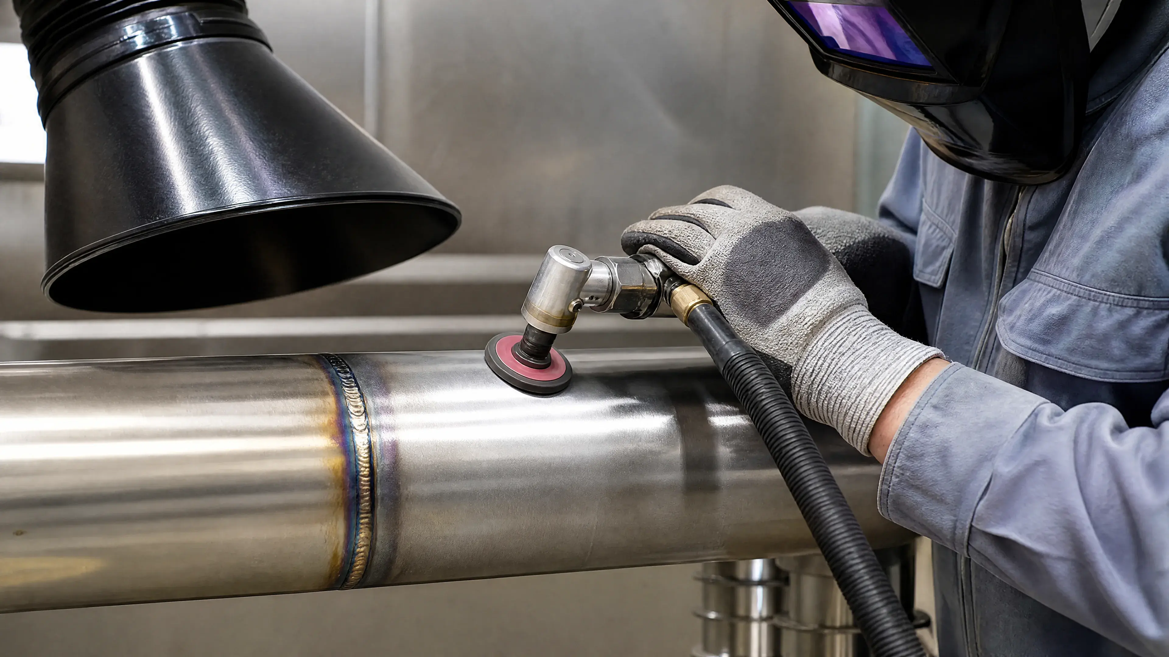
Mechanical blending must preserve minimum thickness and the required weld section. Pickling or electrolytic cleaning must reach the entire treated zone and be fully rinsed. Passivation follows the approved cleaning route when specified. Final texture readings should identify whether they apply to parent metal, weld, toe transition, or all three [9][10][11][12].
4. Performance and hard limits
What a controlled finish can establish
A controlled finish can provide repeatable topography, defined visual quality, a cleanable geometry when combined with suitable equipment design, and an auditable surface-treatment record. It can reduce sharp peaks or blend transitions and can support consistent inspection. Its evidence is strongest when measurements are taken at the actual critical zones on production-equivalent parts [3][4][5][6][7].
What a finish cannot establish
A finish cannot prove material identity, regulatory suitability, weld integrity, complete drainage, or access by itself. It cannot convert an unsuitable alloy into a suitable one, eliminate a hidden overlap, repair a crack, or make an undocumented coating compliant. Each of those outcomes belongs to a separate specification and verification step [1][2][3][4][8][11].
There is no responsible universal statement that one Ra number makes all stainless equipment “food grade.” A jurisdiction, customer standard, equipment type, and contact condition may impose different criteria. Even when a project sets a roughness limit, isolated defects and geometry still require independent acceptance [1][3][5][6][7].
Corrosion and service limits
A properly finished and cleaned passive surface can support corrosion control, but finish does not replace alloy selection or equipment geometry. Comparative studies show that polishing route and alloy influence passive-layer composition and localized-corrosion measurements; they do not support a universal claim that one finish is always superior [8][9][10][15][16].
Passivation evidence confirms only the defined treatment and verification method. It is not an unlimited corrosion warranty or a regulatory declaration for the complete article. Material selection, fabrication, treatment, final rinse, handling, and service conditions remain linked [1][8][9][10].
Appearance limits
Visual sheen is not a roughness measurement. Two surfaces can look similar under one light and have different directional profiles; two surfaces with similar measured roughness can have different color or gloss. Appearance-critical equipment should use controlled lighting, a signed physical sample, and separately stated texture and defect limits [5][6][7].
Local weld blending, pickling, or repair can leave a visible halo even when technical acceptance is met. If uniform appearance matters, the approved sample should include the same alloy heat, weld filler, finishing route, and viewing conditions as production [9][10][12].
5. Material and component compatibility
The stainless grade applies only to stainless components covered by its material record. Elastomeric seals, polymer guides, lubricants, adhesives, sight materials, coatings, and marking systems require their own compliance evidence for the intended jurisdiction and contact conditions. A compliant stainless shell does not extend its status to attached materials [1][2][3].
Mixed stainless grades can be appropriate but need a documented reason and separate traceability. A 316L wetted component joined to 304 structural support may be acceptable in one design, while an exposed 304 fastener in a more severe zone may not be. The contact-zone map should identify material boundaries and damaged-coating or crevice risks [1][8].
Castings and forgings can contain surface features different from rolled sheet and may require machining or finishing to meet the same defect and texture requirements. Thin sheet can distort during welding or polishing; heavy sections can create broad heat-affected regions. Qualification samples should match the production form and thickness [8][11][12].
Coated or lined contact surfaces should not be accepted under a stainless-finish specification. The coating or lining needs its own composition, adhesion, continuity, thickness, repair, and regulatory evidence. Masked stainless boundaries and coating terminations require explicit inspection [1][2][3].
6. Inspection and acceptance
Documentation review
Verify the applicable market and project requirements first. Review material certificates, heat or batch traceability, component declarations, drawings, contact-zone map, welding procedures, inspection plan, finish procedure, chemical-treatment records, nonconformance history, and final certificate wording. Documentation should identify what is being declared and under which jurisdiction [1][2][3][8].
Visual and tactile geometry inspection
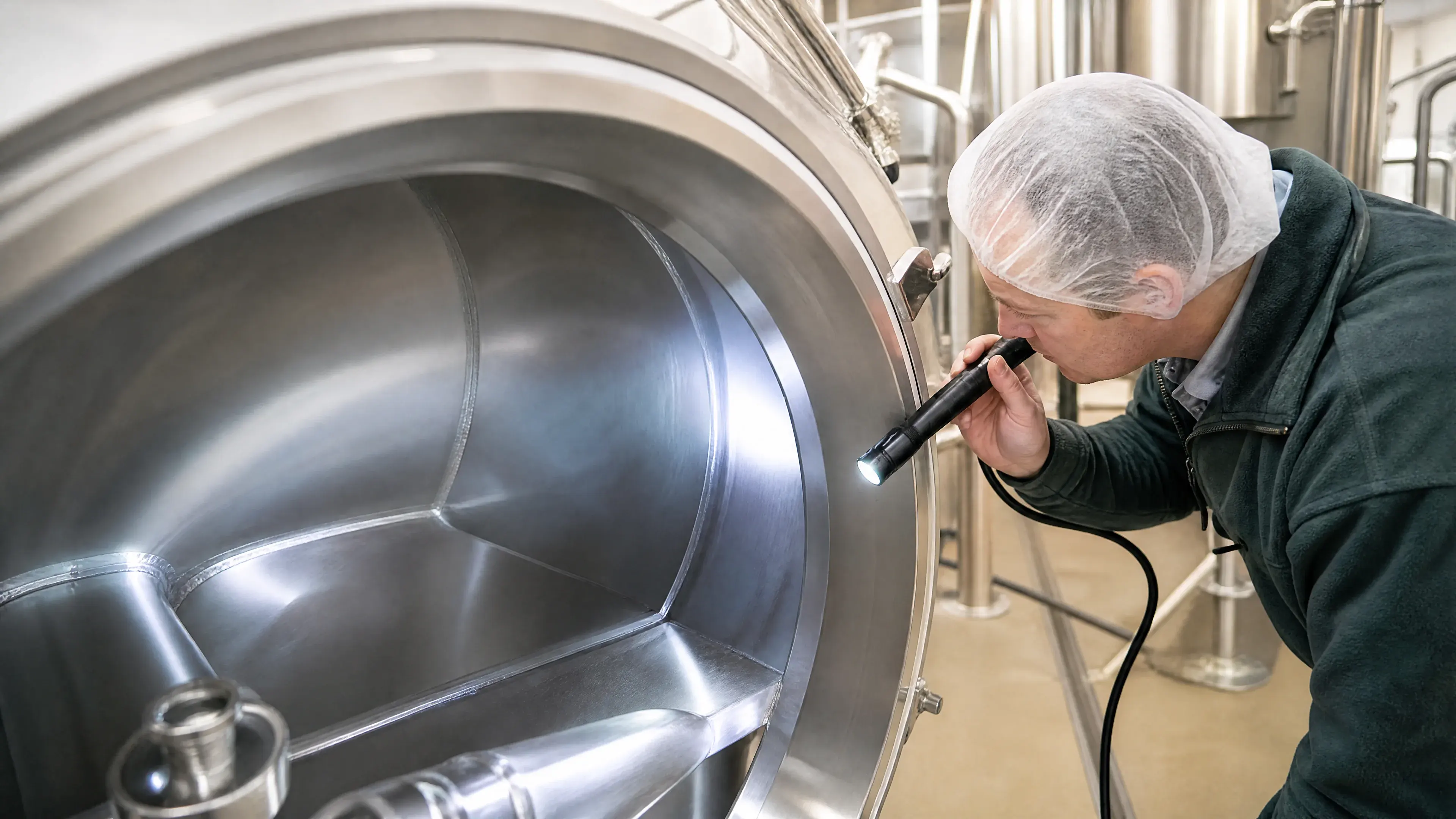
Inspect the actual contact zones under controlled light for cracks, pits, folds, burrs, sharp projections, open seams, incomplete blends, grinding gouges, residual heat tint, chemical streaks, embedded particles, and coating encroachment. Use suitable magnification and physical defect limits. Do not use a bare hand as the sole sharp-edge or smoothness test [3][4][9][10].
Verify weld contour and visible quality at the required stages under ISO 17637 or the governing method. Apply ISO 5817 quality levels only when the design invokes them. A final polished appearance cannot substitute for recorded weld inspection [11][12].
Surface-texture measurement
Calibrate and verify the instrument, select a probe or optical method suited to the surface, and measure at drawing-defined sites and directions. Record individual results, settings, and location identity. Curved or inaccessible zones may need an approved replica or noncontact approach; a flat witness coupon is valid only after correlation to the production surface [5][6][7][13].
Profile and areal results should not be mixed without definition. Report the actual parameter symbol and standard, not the generic phrase “roughness passed.” If an isolated feature has its own limit, record that inspection separately from the average parameter and at a scale suited to the feature [5][6][7][13][14].
Geometry, drainage, and access verification
Inspect installed slopes, low points, tube branches, joint transitions, seal compression zones, removable parts, tool clearance, and observation access against the approved drawing. Demonstrate drainage through the project’s specified geometric or functional method, using production orientation and support conditions [3][4].
Access verification should document how every contact surface is reached or removed for inspection and cleaning. If acceptance relies on a system-level method rather than direct access, the purchaser must define its validation evidence. A polished but inaccessible zone remains a design question [2][3][4].
Chemical surface and release inspection
After fabrication and mechanical finishing, apply the specified cleaning, pickling, and passivation route under ASTM A380/A380M, ASTM A967/A967M, or the approved project procedure. Verify rinse, residue, and post-treatment protection through the named method; do not invent a universal threshold [9][10].
Define lot size, sampling, destructive versus nondestructive tests, failed-lot disposition, and rework limits. Reprocessing can change roughness, dimensions, weld contour, and appearance, so a failed result should trigger documented review before another cycle [5][9][10][12].
7. Practical procurement and manufacturing workflow
- Map regulatory scope. Identify the destination market, adopted requirements, customer specifications, contact zones, and intended contact conditions [1][2][3].
- Select materials. Specify stainless and every nonmetallic contact material through the applicable material or compliance record [1][3][8].
- Complete equipment-design review. Resolve drainage, access, joints, corners, seals, removable parts, instrument connections, and inspection routes before release [3][4].
- Define weld and fabrication quality. State joint details, visual/NDT stages, ISO 5817 quality level if applicable, repair route, and final contour [11][12].
- Define finish by zone. Name the process route, texture parameters, defect limits, lay, appearance sample, measurement sites, and chemical treatment [5][6][7][9][10].
- Qualify representative samples. Use production grade, product form, thickness, weld, geometry, and finish sequence.
- Control manufacturing. Protect contact surfaces, use approved tools and media, preserve traceability, and observe inspection hold points [2][9][10][12].
- Finish and chemically treat. Complete authorized blending, cleaning, descaling, passivation, rinsing, drying, and protected handling [9][10].
- Inspect the assembled condition. Verify documents, welds, texture, defects, geometry, drainage, access, residues, and appearance under the sampling plan [3][4][5][11][12].
- Release with precise records. State the actual material, finish procedure, tests, lots, deviations, and governing requirements rather than certifying only “food grade” [1][2][3].
This workflow treats the finished equipment—not an isolated polish coupon—as the deliverable. A coupon can qualify a tool sequence or measurement method, but it cannot prove drainage, weld access, assembled joints, or the identity of every contact component [3][4][5][8].
8. Finish options and tradeoffs
Mill 2B or another controlled mill finish may be acceptable when the project permits it and fabrication preserves the required surface. It avoids unnecessary removal but can show coil variation and becomes locally different after welding or repair. Acceptance still needs measured texture and defect rules [5][6][7][8].
Directional mechanical polishing provides a repeatable visual lay and can blend fabricated areas. Measurement direction is critical, and cross-grain repair marks can remain visible. Abrasive contamination, compound residue, edge rounding, wall-thickness loss, and the resulting passive-surface condition require control [5][6][9][15][16].
Nondirectional mechanical finishing can reduce visible directional mismatch on some geometries. It does not eliminate the need to define texture, defects, or cleaning. Tool path and overlap can still create local patterns that a single Ra trace misses [5][7].
Electropolishing removes metal electrochemically and can reduce microscopic peaks while changing the passive surface. Its result depends on alloy and process, so a material-removal allowance, current-distribution control, access, rinsing, and corrosion-relevant verification are required; it does not repair poor weld geometry, hidden seams, or drainage [4][5][9][10][15][16].
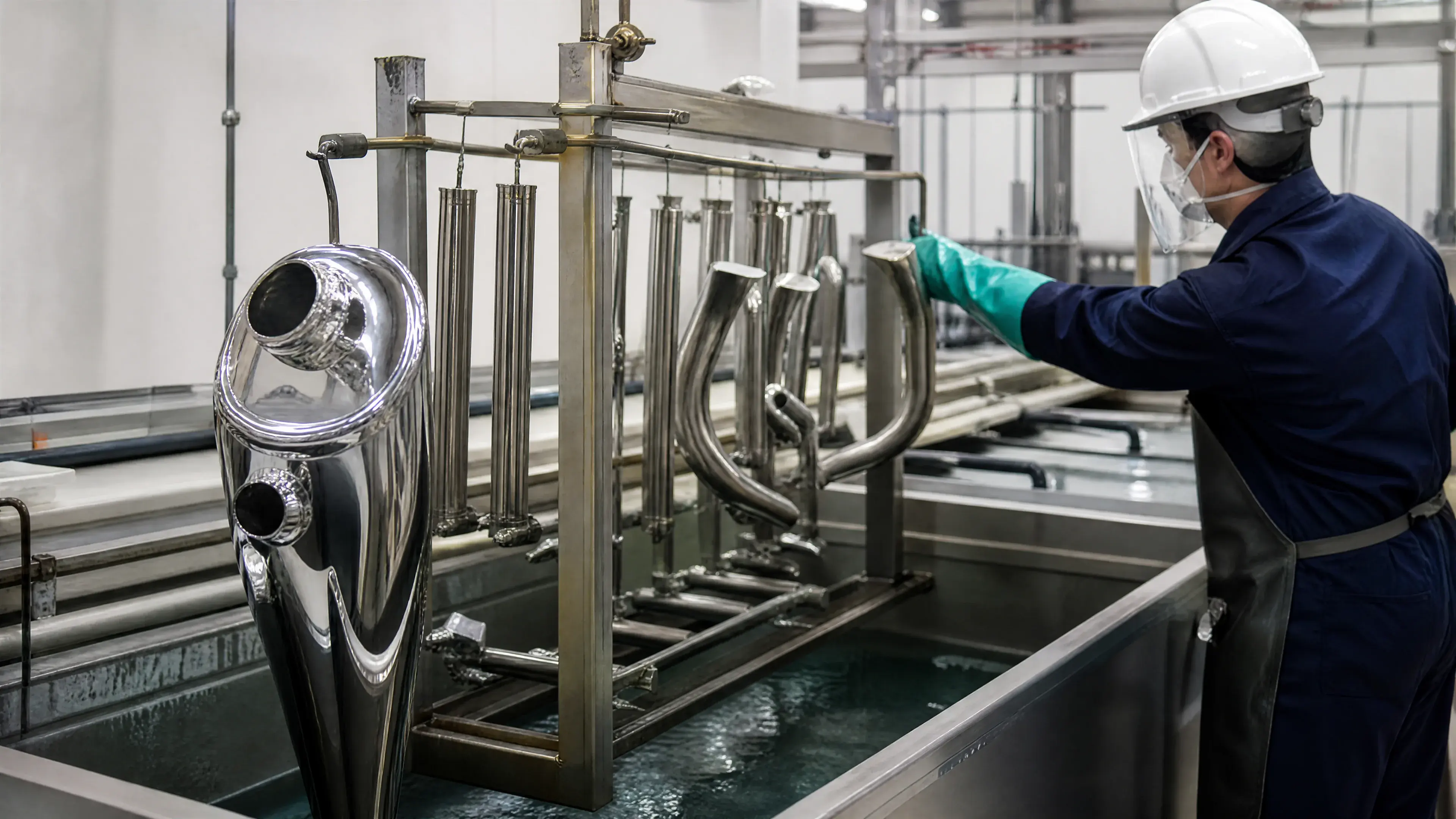
Pickling and passivation address oxide, foreign iron, and passive condition rather than serving as a topographic finish. They may follow welding and mechanical work, but they do not establish a roughness value. Chemical compatibility, drainage, rinse access, and residue control remain part of the equipment design [9][10].
Blasted or textured finishes can create a nondirectional appearance but increase dependence on media identity, profile control, dust removal, and defect inspection. They should be used only when the project’s measured texture and cleaning-access requirements are demonstrated on production-equivalent geometry [5][7][9].
9. Typical applications
Contact vessels and fabricated tanks
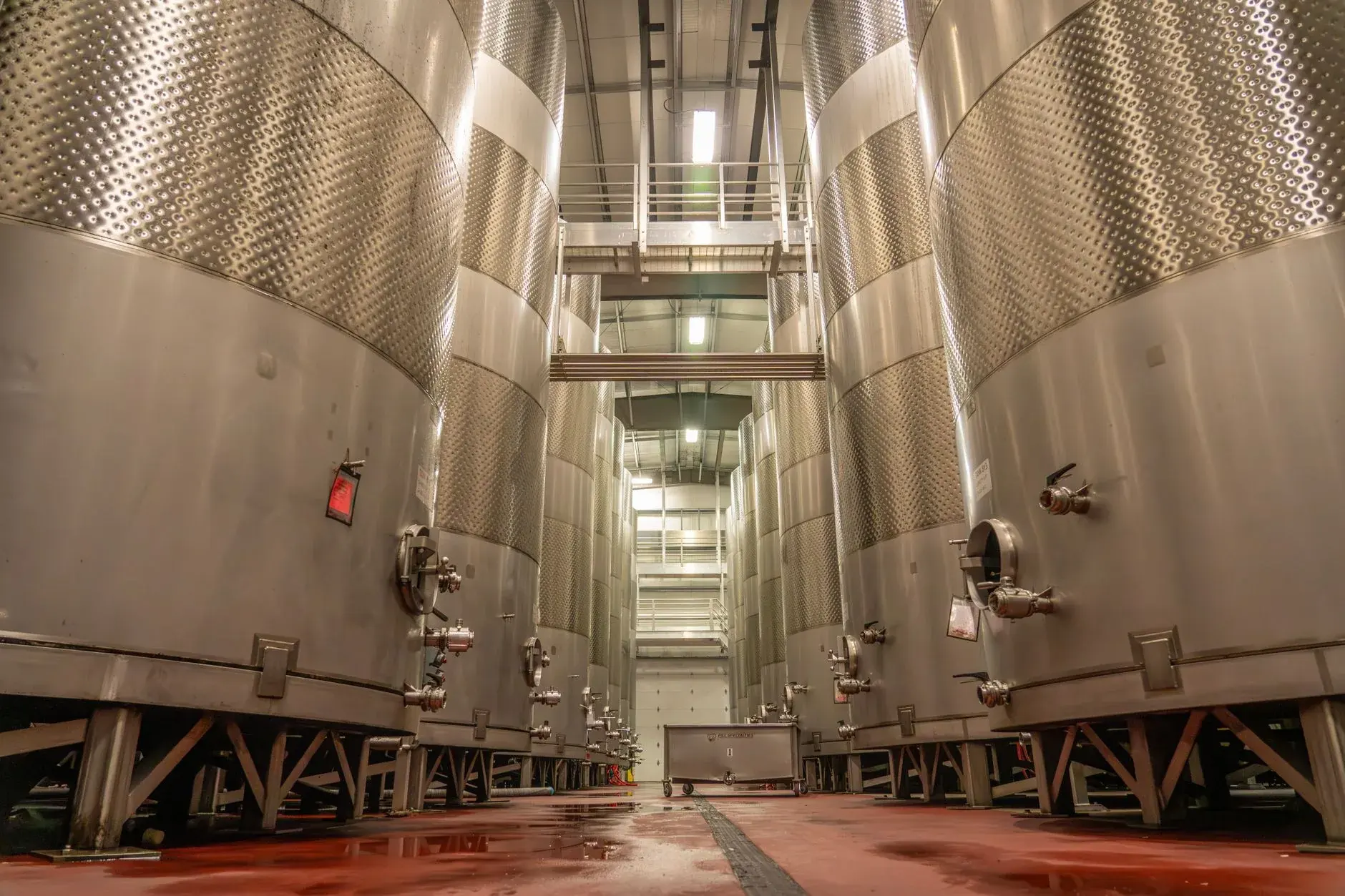
Requirements usually span sheet finish, internal weld contour, no unacceptable low points, outlet geometry, instrument connections, and final chemical treatment. Inspection should cover the assembled interior rather than rely only on incoming sheet records [3][4][8][9][11][12].
Stainless transfer tubing and manifolds
Tube bore finish, root weld geometry, purge condition, branch transitions, slope, support-induced deformation, and inspection access all matter. External polish does not establish internal acceptance. Drawings should identify bore measurement and visual-inspection locations [3][4][5][11][12].
Open contact tables, chutes, and guards
Large visible surfaces need controlled flatness, drainage direction, corner and edge design, weld blending, scratch limits, and replaceable-component interfaces. Directional finishes require consistent lay across panels and repairs [3][4][5][6].
Valves, fittings, and removable components
Cast or machined bodies, seats, seals, threads, clamp interfaces, and internal transitions may follow different material and finish routes. Component declarations and contact-zone drawings should cover the complete assembled item, with roughness and defect checks at the actual functional surfaces [1][3][5][7][8].
10. RFQ checklist
- Destination market, adopted regulations or codes, customer specifications, and responsible compliance authority [1][2][3].
- Contact-zone map, intended contact conditions, temperature, chemistry, duration, and cleaning-method constraints.
- Stainless grade, product form, material standard, heat/batch traceability, filler, fasteners, and every nonmetallic contact material [1][3][8].
- Equipment geometry requirements for slopes, low points, corners, joints, seals, removability, drainage, and inspection access [3][4].
- Weld procedure, joint detail, visual/NDT hold points, ISO 5817 quality level if applicable, repair route, and final contour [11][12].
- Finish route by zone: mill, directional or nondirectional mechanical finish, electropolish, blast, pickling, and passivation.
- Surface-texture parameter, ISO edition, filter/specification operator, evaluation length or area, direction, sites, sampling, and individual-reading rule [5][6][7].
- Separate limits for pits, scratches, folds, burrs, seams, residual tint, embedded debris, edge radius, and wall-thickness reduction.
- Appearance requirements with controlled lighting, grain direction, blend width, and signed physical sample.
- Cleaning, descaling, and passivation standard and edition; rinse, residue, drying, protection, and packaging requirements [9][10].
- First-article scope using production material, welds, corners, formed zones, access constraints, and assembled orientation.
- Required certificates, material declarations, weld map, inspection reports, measurement data, treatment lot, deviations, and failed-lot disposition [1][2][3].
11. Frequently asked questions
Is 304 automatically food grade?
No. 304 is a stainless family designation, not a complete equipment approval. Suitability depends on verified material, contact conditions, jurisdiction, equipment geometry, fabrication, other contact materials, finish, and documentation. More corrosion-resistant grades may be required for some environments, but grade selection remains project-specific [1][3][8].
Is there one universal Ra requirement for every food-contact surface?
No. A project may impose a specific limit, but no single number establishes universal compliance for all equipment and jurisdictions. The parameter and measurement method must be defined, and local defects, weld geometry, drainage, and access need separate acceptance [3][4][5][6][7].
Does electropolishing make equipment compliant by itself?
No. Electropolishing can change topography and passive-surface condition, but it does not prove material identity, weld quality, drainage, access, nonmetallic-material compliance, or jurisdictional acceptance. It is one controlled manufacturing step within the complete equipment specification [1][3][4][5][9][10].
Can a polished weld be accepted without weld inspection?
No. Final polishing can alter or conceal visible evidence. Required visual or other nondestructive inspection should occur at defined hold points under the governing fabrication requirements, and authorized repairs require reinspection before final surface release [11][12].
References
- European Parliament and Council. Regulation (EC) No 1935/2004 on materials and articles intended to come into contact with food. https://eur-lex.europa.eu/eli/reg/2004/1935/oj. Access note: official consolidated-access endpoint verified through EUR-Lex; legal applicability and current amendments require project counsel or regulatory review.
- European Commission. Commission Regulation (EC) No 2023/2006 on good manufacturing practice for materials and articles intended to come into contact with food. https://eur-lex.europa.eu/eli/reg/2006/2023/oj. Access note: official EUR-Lex endpoint verified; this article does not reproduce or interpret protected customer requirements.
- U.S. Food and Drug Administration. Food Code 2022. https://www.fda.gov/food/fda-food-code/food-code-2022. Access note: official FDA page verified; the Food Code is a model code, and adoption or modification by the relevant authority must be confirmed for each project.
- International Organization for Standardization. ISO 14159:2002, Safety of machinery — Hygiene requirements for the design of machinery, Edition 1, published 2002-04. https://www.iso.org/standard/23748.html. Access note: title, edition, publication date, and active “Published” status verified in the official ISO catalogue; a revision project is in development, and protected standard text was not accessed.
- International Organization for Standardization. ISO 21920-2:2021, Geometrical product specifications (GPS) — Surface texture: Profile — Part 2: Terms, definitions and surface texture parameters, Edition 1, published 2021-12. https://www.iso.org/standard/72226.html. Access note: title, edition, publication date, and active “Published” status verified in the official ISO catalogue; protected standard text was not accessed.
- International Organization for Standardization. ISO 21920-3:2021, Geometrical product specifications (GPS) — Surface texture: Profile — Part 3: Specification operators, Edition 1, published 2021-12. https://www.iso.org/standard/72228.html. Access note: title, edition, publication date, and active “Published” status verified in the official ISO catalogue; protected standard text was not accessed.
- International Organization for Standardization. ISO 25178-2:2021, Geometrical product specifications (GPS) — Surface texture: Areal — Part 2: Terms, definitions and surface texture parameters, Edition 2, published 2021-12. https://www.iso.org/standard/74591.html. Access note: title, edition, publication date, and active “Published” status verified in the official ISO catalogue; protected standard text was not accessed.
- ASTM International. ASTM A240/A240M-25a, Standard Specification for Chromium and Chromium-Nickel Stainless Steel Plate, Sheet, and Strip for Pressure Vessels and for General Applications. https://doi.org/10.1520/A0240_A0240M-25A. Access note: official DOI and title metadata verified; protected composition, property, finish, and tolerance tables were not accessed or reproduced.
- ASTM International. ASTM A380/A380M-25, Standard Practice for Cleaning, Descaling, and Passivation of Stainless Steel Parts, Equipment, and Systems. https://doi.org/10.1520/A0380_A0380M-25. Access note: official DOI and current-edition metadata verified; protected recipes, tables, clauses, and acceptance values were not accessed or reproduced.
- ASTM International. ASTM A967/A967M-25, Standard Specification for Chemical Passivation Treatments for Stainless Steel Parts. https://doi.org/10.1520/A0967_A0967M-25. Access note: official DOI and current-edition metadata verified; protected treatment and acceptance details were not accessed or reproduced.
- International Organization for Standardization. ISO 5817:2023, Welding — Fusion-welded joints in steel, nickel, titanium and their alloys (beam welding excluded) — Quality levels for imperfections, Edition 4, published 2023-02. https://www.iso.org/standard/80209.html. Access note: title, edition, publication date, and active “Published” status verified in the official ISO catalogue; protected tables and clause text were not accessed.
- International Organization for Standardization. ISO 17637:2016, Non-destructive testing of welds — Visual testing of fusion-welded joints, Edition 2, published 2016-12. https://www.iso.org/standard/67259.html. Access note: title, edition, publication date, and active “Published” status verified in the official ISO catalogue; protected standard text was not accessed.
- Mínguez-Martínez, A., Maresca, P., Caja, J., & de Vicente y Oliva, J. “Results of a Surface Roughness Comparison between Stylus Instruments and Confocal Microscopes.” Materials, 15 (2022), 5495. https://doi.org/10.3390/ma15165495. Access note: open-access full text reviewed through PubMed Central (PMC9410296); use is limited to metrology method, calibration, and instrument-comparison considerations.
- Bartkowiak, T., Grochalski, K., Gapiński, B., & Wieczorowski, M. “Discrimination of Surface Topographies Created by Two-Stage Process by Means of Multiscale Analysis.” Materials, 14 (2021), 7044. https://doi.org/10.3390/ma14227044. Access note: open-access full text reviewed through PubMed Central (PMC8624860); its steel-ring finishing results support multiscale surface characterization, not a food-contact performance claim.
- Rokosz, K., Solecki, G., Mori, G., Fluch, R., Kapp, M., & Lahtinen, J. “Effect of Polishing on Electrochemical Behavior and Passive Layer Composition of Different Stainless Steels.” Materials, 13 (2020), 3402. https://doi.org/10.3390/ma13153402. Access note: open-access full text reviewed through PubMed Central (PMC7435799); results are used to show alloy- and process-dependent passive-surface behavior, not a universal finish ranking.
- Messinese, E., Casanova, L., Paterlini, L., Capelli, F., Bolzoni, F., Ormellese, M., & Brenna, A. “A Comprehensive Investigation on the Effects of Surface Finishing on the Resistance of Stainless Steel to Localized Corrosion.” Metals, 12 (2022), 1751. https://doi.org/10.3390/met12101751. Access note: open-access full text reviewed; study results support finish-dependent corrosion verification and are not converted into a universal food-contact limit.
Continue the specification
Related surface-finish guides
Specify before production
Need a finish quoted against a drawing or control sample?
Send the material grade, product form, finish requirement, inspection method and quantity. We will identify the unresolved specification points before quoting.
Discuss the requirement