Stainless steel surface engineering
No.4 Brushed Stainless Steel Finish: How to Specify Texture, Match Appearance, and Verify the Result
In this guide
TL;DR
No.4 is best treated as a family of directional, mechanically finished stainless-steel surfaces, not as a universal grit recipe. The name indicates a satin appearance with visible linear lay, but it does not by itself fix the starting surface, abrasive...
1. What the No.4 designation communicates
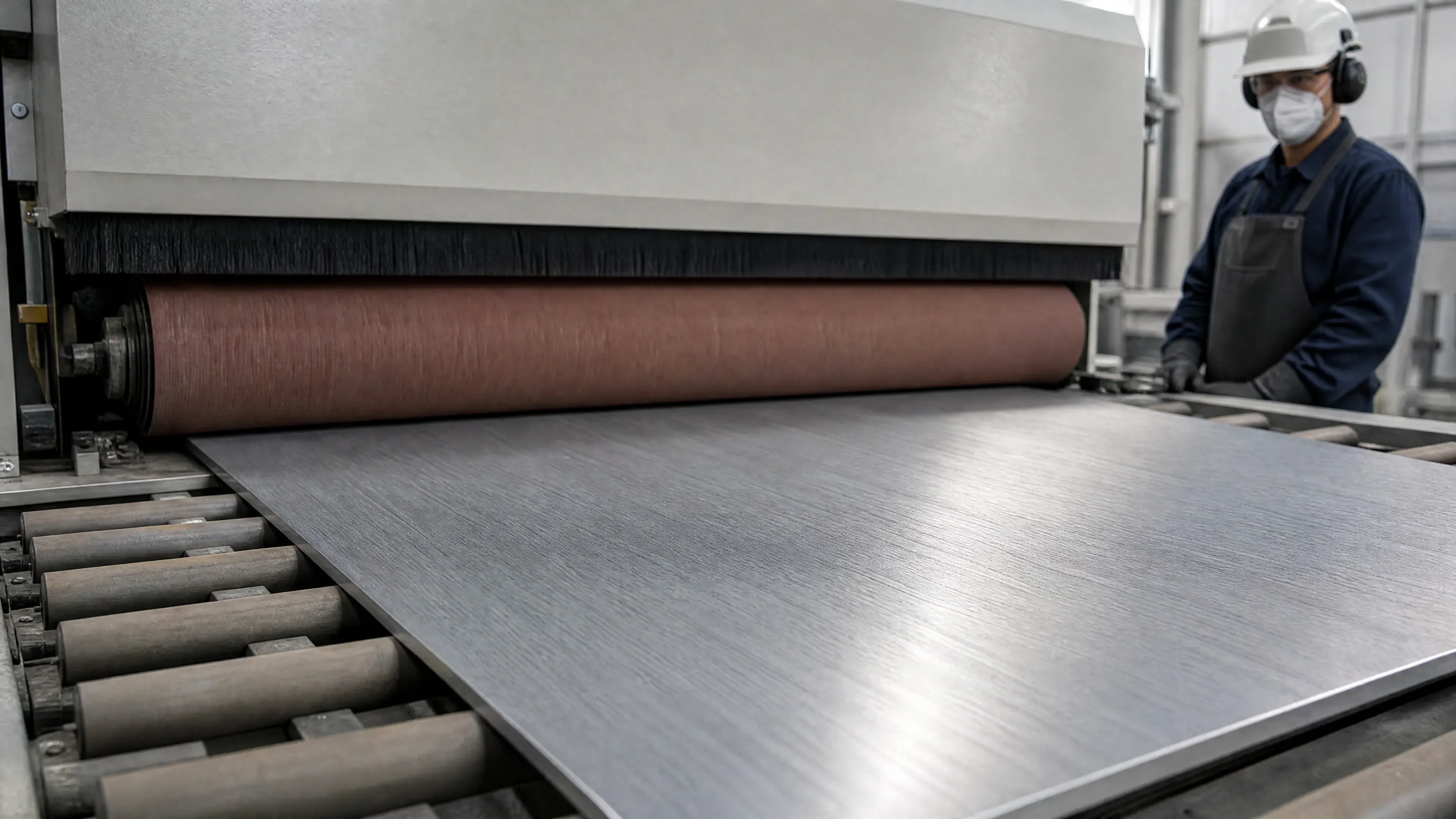
In normal purchasing language, No.4 points to a mechanically produced, directional satin finish. The linear character distinguishes it from a non-directional mill finish, a uniformly blasted matte surface, and a highly reflective mirror-polished surface. That shared vocabulary is useful because it narrows the visual family. It is not a complete acceptance specification.
The final result depends on the surface that entered the finishing operation. A cold-rolled sheet, a welded fabrication, a ground plate, and a formed component can respond differently to the same nominal abrasive. Previous scratches, roll marks, scale, heat tint, waviness, and local work hardening may remain visible or influence how quickly material is removed. The finisher may need several preparation stages before applying the pass that creates the final visible lay.
Process variables then add another layer. Abrasive mineral and construction, nominal grade, belt or wheel condition, contact-wheel hardness, pressure, feed speed, overlap, heat generation, lubrication, and operator path can all affect line character and topography. An inspected abstract concerning flap-wheel finishing of stainless cookware identified several controllable grinding variables rather than a one-variable grit-to-roughness relationship [8]. Because only the abstract was available, it supports the multi-variable point but no transferable recipe or numerical target.
Geometry also matters. A route qualified on a flat coupon may not reproduce the same appearance on a tight return, inside corner, narrow flange, weld transition, or large panel. The designation should therefore be read as the beginning of a conversation about the required result, not as permission to leave every production variable unstated.
2. No.4 is not one universal grit or roughness value
Nominal abrasive grade describes an abrasive product, while surface roughness describes a measured profile after a complete process. The two are related, but they are not interchangeable. A new abrasive and a worn abrasive bearing the same designation can cut differently. A harder contact wheel, another feed rate, a second pass, or a different starting finish can change the result without changing the nominal grade.
For that reason, an instruction such as “finish with 180 grit” does not fully define a No.4 surface. It omits the abrasive system, machine condition, direction, overlap, starting material, preparation stages, and acceptance method. Conversely, a single Ra limit does not define the visible density, continuity, color, gloss, or straightness of the grain. A part can satisfy a roughness number and still fail to match an approved panel.
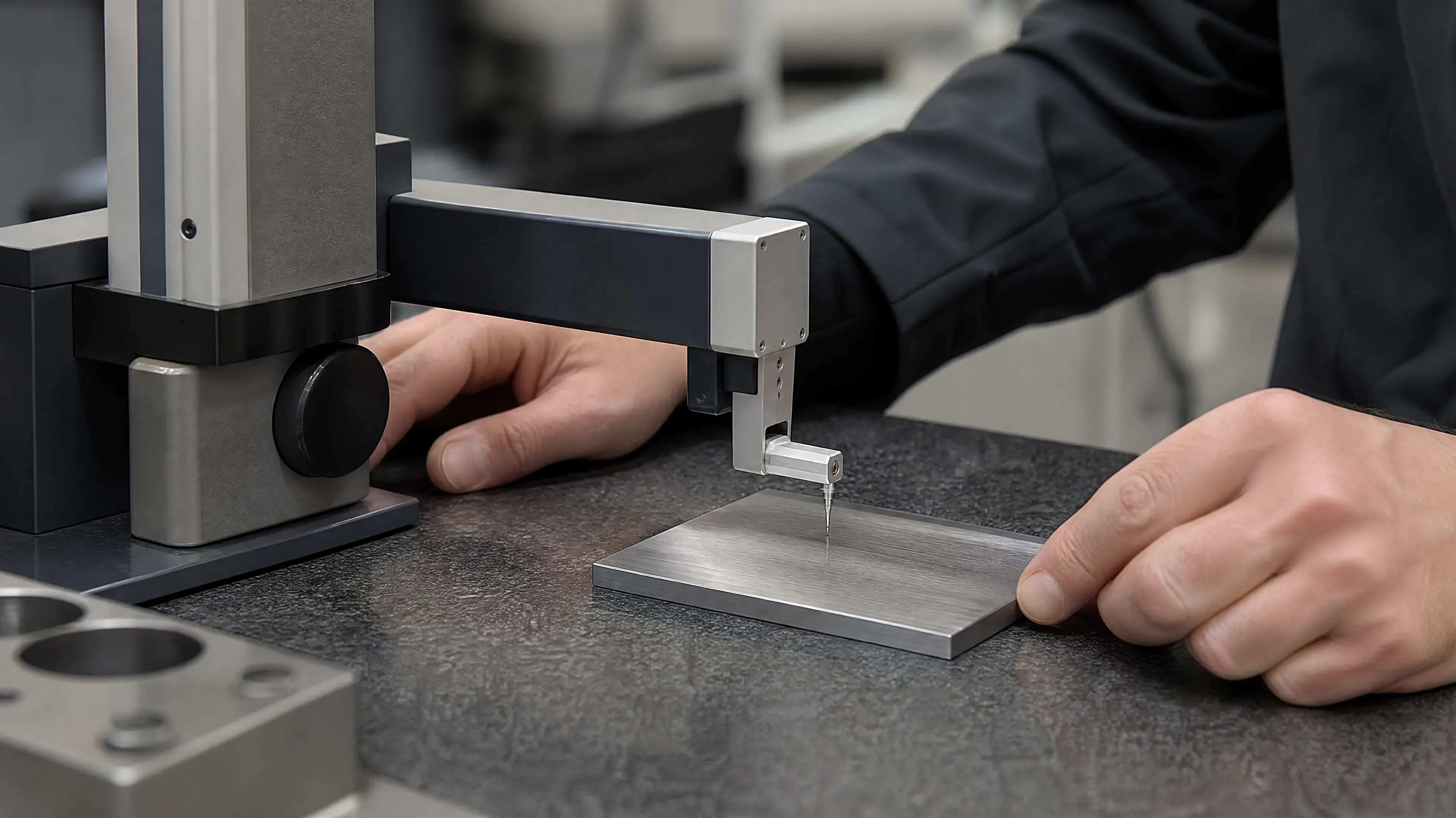
If texture is functional, the drawing should name the parameter and units, measurement direction relative to the lay, instrument type, filtering or cutoff settings, evaluation length, locations, number of readings, and acceptance statistic. The method belongs in the requirement because a bare number does not identify how the profile was acquired or evaluated. None of the reviewed No.4 sources establishes a universal measurement limit.
Measure direction deliberately. A trace along the grain can cross fewer ridges than a trace across it and can answer a different question. If both directions matter, state both. If only appearance matters, a physical reference and controlled viewing procedure may be more honest than inventing a roughness limit that has no functional basis.
3. Separate appearance, texture, and performance
A robust specification has three acceptance tracks.
Appearance acceptance asks whether the part matches the intended line character, reflectivity, uniformity, direction, and adjacent pieces. It is evaluated against an approved physical surface under agreed lighting, distance, angle, and cleanliness. Photographs help communication, but exposure, white balance, compression, screen brightness, and viewing angle make them weak as the sole final standard.
Texture acceptance asks whether a declared parameter meets a declared limit when measured by a declared method. It needs trace locations, instrument settings, direction, sample count, and a rule for isolated scratches or outliers. An average value does not describe every valley, ridge, pit, overlap mark, or long-wavelength waviness, so visual defect criteria remain necessary when those features matter.
Performance acceptance asks whether the alloy, fabricated condition, cleaning state, finish, and service qualification are suitable for the actual exposure. A decorative reference panel cannot prove resistance to a chloride environment. A roughness reading cannot prove that a weld has been adequately cleaned. A process traveler proves what was recorded, not automatically how the part will perform in service.
Keeping these tracks separate makes a disagreement diagnosable. The parties can determine whether a failure concerns visual matching, measured texture, contamination, material identity, fabrication condition, or service qualification instead of arguing about the undefined word “brushed.”
4. What corrosion research can and cannot establish
Two inspected full-text studies show why surface-finish claims need narrow boundaries. Messinese and co-workers compared cold-drawn and ground bars across several stainless alloys and corrosion tests [1]. Rokosz and co-workers compared defined mechanically and electrochemically polished conditions while examining electrochemical behavior and passive-layer composition [2]. Both demonstrate that finishing route sits inside a larger system that includes alloy, starting condition, process chemistry, and test environment.
The Messinese study reported improved localized-corrosion results after grinding for the specific cold-drawn bars, alloys, and exposure combinations tested [1]. That finding is relevant to the importance of prior processing and subsequent finishing. It is not a production qualification for commercial No.4 sheet, and it cannot be converted into the statement that every ground decorative surface outperforms every mill surface.
The Rokosz study provides a complementary caution. Under its defined materials, mechanical-polishing condition, electropolishing route, and severe chloride testing, a smoother or more reflective route did not create one uniform advantage across all tested conditions [2]. The defensible lesson is that appearance alone does not establish corrosion performance. The paper is not a direct comparison of commercial No.4 products.
An inspected publisher abstract by Burstein and Pistorius reported a non-simple relationship between roughness and pitting for Type 304 in the chloride solutions studied: the abstract described fewer metastable events on smoother surfaces but a greater chance that an event would become stable [6]. No uninspected method, value, or broader conclusion is imported here. The result is useful mainly because it blocks a simplistic “smoother always means better” rule.
Four additional DOI records concern surface finish, roughness, cleaning, pitting, or machining [3][4][5][7]. Where only metadata was available, their titles are not used as evidence of a result. A buyer requiring corrosion performance should name the applicable alloy, fabricated state, exposure, test method, acceptance threshold, and sampling plan rather than use the finish name as a proxy.
5. Build the visual target before production
The most direct visual control is an approved physical sample made from representative material. Give the sample a stable identifier and revision. Record its grade, thickness, starting surface, finishing date, controlled face, and grain direction. Protect it from handling damage and contamination so that it remains a useful comparator.
Choose a sample size that represents the risk. A hand-sized coupon may communicate general line character, but it may not reveal long streaks, overlap bands, waviness, or transitions created across a large sheet. Architectural panels, appliance fronts, and broad enclosures may require a full-size first article or an assembled mockup under the intended light.
Agree how the comparison will be made. State whether inspection occurs after protective film removal, after cleaning, and before or after assembly. Define the principal light direction, viewing distance, viewing angle, and whether raking light is part of normal acceptance. Do not create a forensic lighting condition that was never part of the intended service, but do not hide defects behind uncontrolled dim lighting either.
Record permissible variation. A limit sample or paired “acceptable/not acceptable” references can communicate boundaries for grain density, short scratches, overlap lines, shade variation, edge transitions, and repaired areas. Descriptive adjectives alone rarely close those questions.
6. Control grain direction and panel matching
Direction is a design feature of No.4, so orientation must survive the entire manufacturing route. Put a grain arrow on the drawing and tie it to an unambiguous datum, installed vertical, long dimension, or other named feature. Mark parts before cutting and preserve that identity through nesting, forming, assembly, and packaging.
Adjacent panels need more than individual approval. Material from different coils, starting finishes, abrasive lots, machine setups, or production dates can look different even when every panel is called No.4. For critical elevations or appliance groups, state whether adjacent pieces must use one qualified material lot, one finishing batch, and a preserved cutting sequence. Inspect the set in its installed order when the visual risk justifies it.
Corners and seams require a layout decision. Grain lines that meet at ninety degrees may be intentional; a reversed panel may not be. A formed corner can bend the reflected light and make a uniform texture appear different. The approval process should distinguish an optical effect caused by geometry from an actual change in the finish, while still judging the assembled result the customer will see.
Protective film reduces handling damage but can conceal scratches and leave impressions or residue. Specify the controlled faces, film performance, application direction if relevant, removal deadline, storage conditions, and the party responsible for inspection after removal. Film should preserve an approved surface, not postpone definition of that surface.
7. Bends, welds, edges, and repairs
A flat-sheet finish is not automatically reproducible on every fabricated feature. Forming changes local geometry and reflection. Tight bends can stretch or compress the visible texture. Cut edges expose a different surface. Welds add heat tint, weld metal, distortion, and a zone that may require grinding or chemical cleaning.
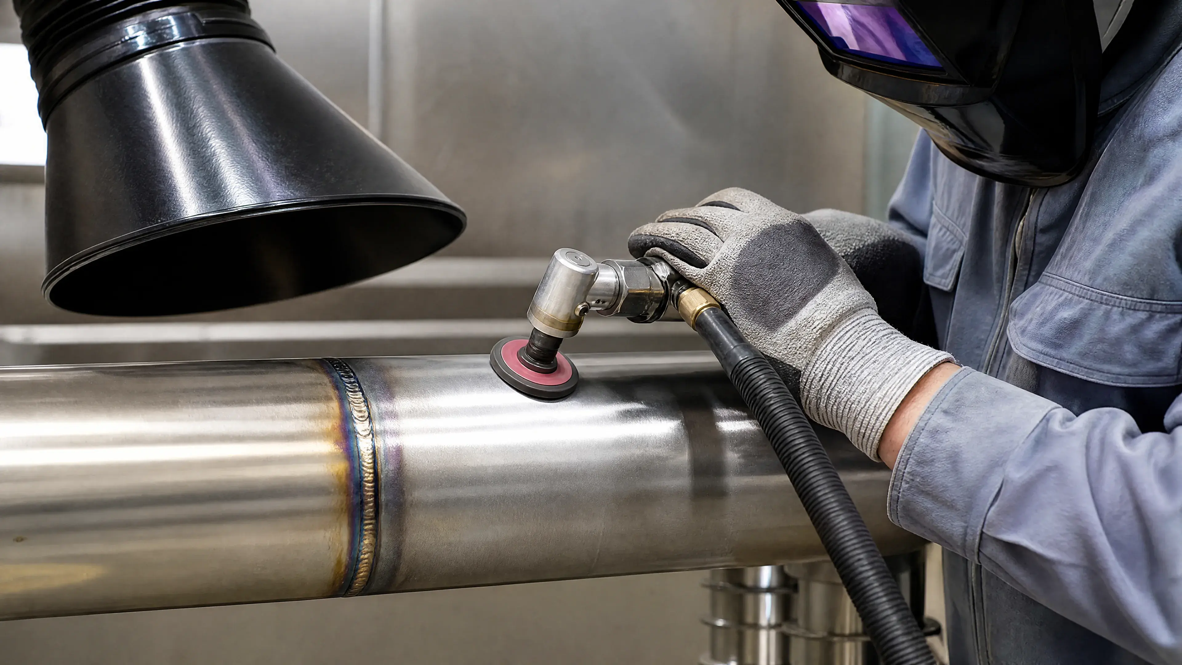
Mechanical blending removes the original texture and creates a new one. On a welded assembly, “restore No.4” should therefore mean “match the approved appearance within the agreed limits,” not “recreate an untouched mill condition.” The fabricator should demonstrate the proposed sequence on a representative weld coupon using the actual grade, thickness, joint, heat input, and accessible tooling.
Repair rules belong in the quotation. Mark zones where local blending is allowed, zones where a complete face must be refinished, and features where repair is prohibited without approval. Define whether a repaired area must be reinspected visually, remeasured, cleaned, or resubmitted as a first article. Record the reason, location, method, and repeat result.
Repeated repair can remove material, round edges, widen transitions, and change flatness. Set an escalation rule rather than allowing indefinite attempts. If invisibility is essential, prove it before production; if it cannot be proved, redesign the finish boundary or accept a deliberate transition.
8. A purchase specification that can be inspected
A practical No.4 callout answers the following questions:
- Material identity: grade, product form, thickness, governing material requirement, and traceability.
- Starting condition: mill finish, prior grinding, welded condition, heat tint, scale, or other relevant history.
- Controlled surfaces: every appearance-critical face, edge, return, and hidden functional area.
- Visual reference: approved sample ID and revision, with representative grade, thickness, and size.
- Orientation: grain arrow tied to a drawing datum and rules for bends, seams, and adjacent parts.
- Viewing method: lighting, distance, angle, cleanliness, assembly state, and film-removal stage.
- Texture measurement: parameter, units, direction, instrument settings, locations, sample count, and acceptance rule where function requires it.
- Defect limits: scratches, pits, dents, streaks, overlap marks, shade variation, waviness, and edge damage.
- Fabrication and repair: weld treatment, corner strategy, permitted repair zones, resubmission, and maximum attempts.
- Lot and protection: matching strategy, part sequencing, film, interleaving, handling, storage, and packaging.
- Release evidence: material record, process traceability, first-article approval, raw measurements, panel map, repair map, and final signoff.
This list lets bidders price the same scope. A quotation that merely says “No.4 included” leaves the most expensive visual and inspection questions unresolved.
9. Inspection workflow
Start with incoming material. Confirm grade, thickness, starting finish, condition, lot identity, and visible damage before value is added. Reserve representative reference material and record which sheets feed appearance-critical parts.
At process qualification, finish a representative coupon or first article. Compare it with the approved reference, verify grain direction, and collect any required texture measurements using the declared method. Record enough process information to repeat the accepted result without pretending that one nominal abrasive designation is the complete recipe.
During production, preserve orientation and part identity. Monitor changes in abrasive condition, machine setup, overlap, and handling that could alter the result. Quarantine parts that need unapproved repair rather than blending them invisibly into the lot.
At final inspection, remove film at the agreed stage, clean by the agreed method, and inspect the whole controlled area under the agreed conditions. Review adjacent panels as a set where required. Link the decision to the drawing revision, sample revision, material lot, measurement report, and repair map.
10. When No.4 is and is not a rational choice
No.4 is a rational option when a directional satin appearance is intentional, the geometry permits controlled finishing, and the supply chain can reproduce the visual target against a retained reference. It can suit visible panels, enclosures, appliances, architectural components, and fabricated equipment when project-specific appearance and functional requirements are written separately.
Choose another strategy when the design needs a non-directional matte field, a clear mirror image, an untouched mill surface, or a service qualification tied to another route. Also reconsider No.4 when extensive weld repair must be invisible but no representative trial demonstrates that outcome.
For hygienic, chemical, marine, or other demanding service, do not let the decorative label decide the complete system. Alloy selection, joint geometry, drainage, defects, contamination control, cleaning, temperature, deposits, and exposure remain separate engineering questions. No.4 may be part of the design, but the evidence reviewed here does not establish a universal food-grade, corrosion-resistant, or maintenance-free finish.
11. Evidence boundaries and publication gaps
Eight peer-reviewed DOI records were verified for this article. Two open full texts were inspected [1][2], two publisher-deposited abstracts were inspected and used only within their explicit scope [6][8], and four records remain metadata-only [3][4][5][7]. Metadata confirms identity and research topic; it does not support a result. Those four sources are retained to show the research boundary, not to lend unsupported authority to the prose.
This article contains no supplier-specific machine, abrasive sequence, achievable roughness range, maximum panel size, lead time, repair success rate, or corrosion guarantee. Any future capability statement requires a controlled first-party record tied to representative material, geometry, equipment, measurement, and approved photography.
12. Buyer checklist
- Is the visual target represented by an approved physical sample?
- Are material, thickness, starting condition, and controlled faces identified?
- Is grain direction tied to an unambiguous datum?
- Are adjacent-panel sequence and matching requirements written?
- Does any texture limit include a complete measurement method?
- Are viewing light, distance, angle, cleaning, and film removal defined?
- Have bends, edges, welds, corners, and large-area effects been trialed?
- Are permitted repairs, repeat inspections, and escalation rules clear?
- Are corrosion, cleanability, and other functional requirements specified independently?
- Do release records connect the accepted part to its material, sample, process, measurements, and repairs?
References
- Messinese, E., Casanova, L., Paterlini, L., Capelli, F., Bolzoni, F., Ormellese, M., & Brenna, A. “A Comprehensive Investigation on the Effects of Surface Finishing on the Resistance of Stainless Steel to Localized Corrosion.” Metals, 12 (2022), 1751. https://doi.org/10.3390/met12101751. Access note: DOI metadata matched the publisher record; official open full-text PDF was inspected. The tested cold-drawn and ground bars are not commercial No.4 sheet.
- Rokosz, K., Solecki, G., Mori, G., Fluch, R., Kapp, M., & Lahtinen, J. “Effect of Polishing on Electrochemical Behavior and Passive Layer Composition of Different Stainless Steels.” Materials, 13 (2020), 3402. https://doi.org/10.3390/ma13153402. Access note: DOI metadata matched; open full text in Europe PMC was inspected. The defined mechanical and electrochemical routes are not a commercial No.4 comparison.
- Shawesh. “Role of Surface Finish and Post-Fabrication Cleaning on Localised Corrosion of Type 316L Austenitic Stainless Steel Flash Chambers.” British Corrosion Journal (2001). https://doi.org/10.1179/000705901322914250. Access note: Crossref DOI metadata matched title, journal, year, and publisher; no abstract or lawful full text was inspected, so no result from this paper is used.
- Hong, T., & Nagumo, M. “Effect of Surface Roughness on Early Stages of Pitting Corrosion of Type 301 Stainless Steel.” Corrosion Science (1997). https://doi.org/10.1016/S0010-938X(97)00072-3. Access note: DOI metadata matched title, authors, journal, and year; no abstract or full text was inspected, so the record establishes topic only.
- Lee, S. M., Lee, W. G., Kim, Y. H., & Jang, H. “Surface Roughness and the Corrosion Resistance of 21Cr Ferritic Stainless Steel.” Corrosion Science (2012). https://doi.org/10.1016/j.corsci.2012.06.031. Access note: DOI metadata matched title, authors, journal, and year; no abstract or full text was inspected, so no finding is attributed to it.
- Burstein, G. T., & Pistorius, P. C. “Surface Roughness and the Metastable Pitting of Stainless Steel in Chloride Solutions.” Corrosion, 51 (1995). https://doi.org/10.5006/1.3293603. Access note: DOI metadata and publisher-deposited abstract were inspected; use is restricted to the explicit Type 304 chloride-solution statements in that abstract.
- Turnbull, A., Mingard, K., Lord, J. D., Roebuck, B., Tice, D. R., Mottershead, K. J., Fairweather, N. D., & Bradbury, A. K. “Sensitivity of Stress Corrosion Cracking of Stainless Steel to Surface Machining and Grinding Procedure.” Corrosion Science (2011). https://doi.org/10.1016/j.corsci.2011.06.020. Access note: DOI metadata matched title, authors, journal, and year; no abstract or full text was inspected, and no result from it is used.
- Somgumnerd, J., Saetang, V., & Prombanpong, S. “Effects of Flap Wheel Grinding Parameters on Surface Roughness for Stainless Steel.” Applied Mechanics and Materials (2014). https://doi.org/10.4028/www.scientific.net/AMM.548-549.506. Access note: DOI metadata and publisher-deposited abstract were inspected; use is limited to its multi-variable stainless cookware case, with no numerical recipe generalized.
Continue the specification
Related surface-finish guides

Specify before production
Need a finish quoted against a drawing or control sample?
Send the material grade, product form, finish requirement, inspection method and quantity. We will identify the unresolved specification points before quoting.
Discuss the requirement