
Stainless steel surface engineering
How to Specify Surface Finish on Drawings and Purchase Orders
In this guide
TL;DR
A surface-texture symbol is a pointer into a measurement contract, not the whole contract. For a new ISO drawing, identify the applicable ISO 21920 edition and fully define the profile parameter, limit, units, specification operator, direction, and...

1. The Real Job of a Surface-Finish Requirement
A drawing must communicate what surface is required and how conformity will be decided. It should not force a receiving inspector to reconstruct the designer’s intent from a familiar-looking symbol, a process nickname, or a supplier’s house standard.
Surface texture is multiscale. Form, waviness, roughness, lay, local defects, gloss, cleanliness, and passive condition can all matter. A one-number requirement is appropriate only when that number has been shown to protect the function. Peer-reviewed multiscale analysis demonstrates that conventional height parameters do not always discriminate surfaces created by different process histories [8]. A stainless-steel drawing therefore needs a deliberate boundary between texture, appearance, process, defects, and functional performance.
Start with the engineering question:
- Is the surface visible to a customer?
- Does it contact food, pharmaceutical product, a seal, a bearing, or a coating?
- Does texture direction affect flow, sliding, cleaning, fatigue, or light reflection?
- Are welds, edges, repairs, and internal passages included?
- Is the requirement for a new part or a replacement to a legacy drawing?
- Will conformity be determined by measurement, visual comparison, a process record, or a functional test?
The answer determines what belongs on the drawing and what belongs in the purchase order, inspection plan, or controlled reference-sample record.
2. Five Layers of a Complete Specification
Layer 1: the governed surface
Show exactly which faces, zones, welds, edges, bores, or product-contact areas receive the requirement. A global note such as “all surfaces Ra 0.8” can be physically impossible, unnecessarily expensive, and functionally wrong. Use local indications or a clearly keyed zone map.
Layer 2: the texture measurand
State the parameter, limit type, value, and unit. “Ra 0.8 µm maximum” is materially clearer than “finish 0.8.” If both Ra and Rz are required, each needs a purpose. A peer-reviewed interlaboratory study gives Ra as the arithmetic mean of absolute profile height over the evaluation length and treats Rz as an extreme-height parameter that is more sensitive to scratches, dirt, and defects under its cited legacy ISO basis [6]. Current normative definitions and notation must come from the specified current standard, not from memory or a catalog summary.
Layer 3: the specification operator
The reported value depends on filtering or nesting indices, evaluation length, form removal, measurement direction, location, instrument interaction, and data treatment. ISO’s official records identify ISO 21920-2:2021 as the terms, definitions, and parameter part and ISO 21920-3:2021 as the specification-operator part of the current profile-texture series [1][2]. The records establish identity, edition, title, and scope; the licensed standards provide the normative clauses.
Layer 4: non-texture requirements
Appearance, process, cleanliness, passive condition, coating, and prohibited defects are independent controls. A low Ra does not prohibit a dent, color mismatch, cross-grain repair, heat tint, embedded iron, or adhesive residue. A process term such as “electropolished” does not by itself state final roughness, material removal, gloss, cleanability, or corrosion acceptance.
Layer 5: conformity decision
Define instrument competence, sampling, reporting, measurement uncertainty, and the decision rule. JCGM 100:2008 is the international guide for evaluating and expressing measurement uncertainty [5]. NIST Technical Note 1297 provides an official practical implementation for NIST results [7]. Without an agreed decision rule, a result near the limit can be argued both ways.
3. Keep ISO and ASME Systems Separate
ISO-based drawings
For a new ISO-based drawing, identify the selected standards and editions in the drawing’s standards block or controlled specification. ISO 21920-2:2021 covers current profile terms, definitions, and parameters; ISO 21920-3:2021 covers specification operators [1][2]. Use the licensed text when constructing the indication and inspection method.
ISO 1302:2002 was a widely used surface-texture indication standard, but ISO’s official catalog marks it withdrawn [3]. That status creates a legacy-management task. It does not authorize a designer to redraw an old ISO 1302 symbol and silently apply ISO 21920 conditions. For replacement parts, determine which edition governed the original drawing, what the original manufacturing and inspection records show, and whether functional equivalence or literal historical conformance is needed. For new parts, issue a controlled current requirement.
ASME-based drawings
ASME’s official record identifies ASME Y14.36-2018, reaffirmed in 2024, as the standard for surface-texture symbols [4]. ASME describes it as establishing methods to designate controls for roughness, waviness, and lay on drawings and related documents, and states that it does not specify how the surface is produced or measured [4]. That boundary is important: a valid Y14.36 symbol still needs the applicable ASME measurement basis, drawing conventions, and purchase controls.
Do not take a graphical element from ASME, attach an ISO parameter assumption, and let the supplier choose the rest. Likewise, do not place an ISO indication on an otherwise ASME drawing without explicitly controlling the exception. If a global corporate specification translates between the systems, it must identify editions and verified differences rather than calling them “equivalent.”
Units do not select the system
Metric units do not automatically mean ISO, and microinch units do not automatically mean ASME. Either organization’s documents may be used in international supply chains. The title block, standards list, parameter notation, operator, and inspection plan—not the unit alone—establish the system.
4. What Goes on the Drawing
The drawing should carry stable design requirements that affect interchangeability or function:
- surface zones and boundaries;
- parameter names, numerical limits, and units;
- governing standards and editions;
- measurement direction relative to lay or a datum;
- any specified lay direction required for function or installed appearance;
- locations that require distinct treatment, including welds and sealing faces;
- prohibited local defects when they are design-critical;
- reference to the controlled finish specification, inspection plan, or approved sample;
- any functional test that is part of product acceptance.
Avoid putting change-prone shop settings directly on a design drawing unless they are validated special characteristics. Belt speed, abrasive supplier, bath time, or polishing compound may belong in the manufacturer’s controlled work instruction. A design drawing should define the required output and any process restriction that protects a known risk—for example, prohibition of carbon-steel media on a stainless surface.
5. What Goes in the Purchase Order or Finish Specification
The purchase document completes the commercial and quality context:
- base material grade, product form, thickness, condition, and product standard;
- finish designation under a stated finish standard and edition;
- final fabrication sequence, including forming, welding, heat-tint removal, finishing, and cleaning;
- approved process family and prohibited substitutions;
- inspection method, equipment class, calibration status, and reporting format;
- sampling plan by lot, part, zone, and trace;
- approved sample identifier, revision, custody, and replacement process;
- packaging, protective film, handling, and film-removal requirements;
- first-article approval and production-change notification;
- nonconformance, concession, rework, and repair approval route.
The PO should repeat or unambiguously reference the drawing revision. A supplier quotation that says “standard commercial finish” is not acceptance of a controlled texture requirement unless the quote explicitly acknowledges it.
6. Process Names Are Not Acceptance Criteria
“180 grit”
Grit is an abrasive size class. Resulting texture also depends on mineral, belt construction, wear, pressure, speed, feed, lubrication, starting surface, material hardness, and pass sequence. Use grit to control a qualified process, not as a universal Ra conversion.
“No. 4” or another finish designation
A designation is meaningful only within its governing product standard and edition. It may describe route or appearance without fixing every roughness operator, gloss, grain length, defect, or repair condition. If a numerical result is functionally necessary, specify and measure it separately.
“Mirror”
Mirror is an appearance claim unless an optical method and acceptance limit are defined. Ra cannot fully control haze, image clarity, waviness, orange peel, directional lines, or reflected-image distortion. Use a controlled master and appropriate gloss or image-quality measurement when required.
“Passivated”
Passivation is a process family, not a statement that heat tint, scale, roughness, free iron, rinse residue, or corrosion performance has passed. Cite the process standard, method, final cleanliness, and test relevant to the application.
“Electropolished”
Electropolishing is an electrochemical material-removal process. Geometry, current distribution, electrolyte, temperature, time, starting condition, and fixturing affect the result [9]. Put required final texture, material removal, dimensions, defects, cleanliness, and any passive-condition test on the contract.
7. Direction, Lay, and Appearance
Directional stainless surfaces require two coordinate systems: the functional measurement direction and the installed visual grain direction. They may be related but are not the same instruction.
For profile measurement, identify the traverse direction relative to lay or a datum. The same anisotropic surface can report different values along and across its dominant texture. For appearance, show grain arrows through blank cutting, bending, joining, and final installation. Research on 316L surfaces produced by powder-bed fusion found large orientation effects on surface-texture parameters, illustrating the broader principle that direction and manufacturing orientation matter [10].
A visual master should record:
- material grade, thickness, heat or lot if relevant, and starting finish;
- complete fabrication and finishing route;
- grain direction and “viewing side”;
- lighting type, incidence, viewing distance, and viewing angle;
- acceptable variation in gloss, color, and texture;
- unacceptable scratches, dents, chatter, weld-blend halos, edge rounding, and repair marks;
- sample ID, approval signatures, date, and revision.
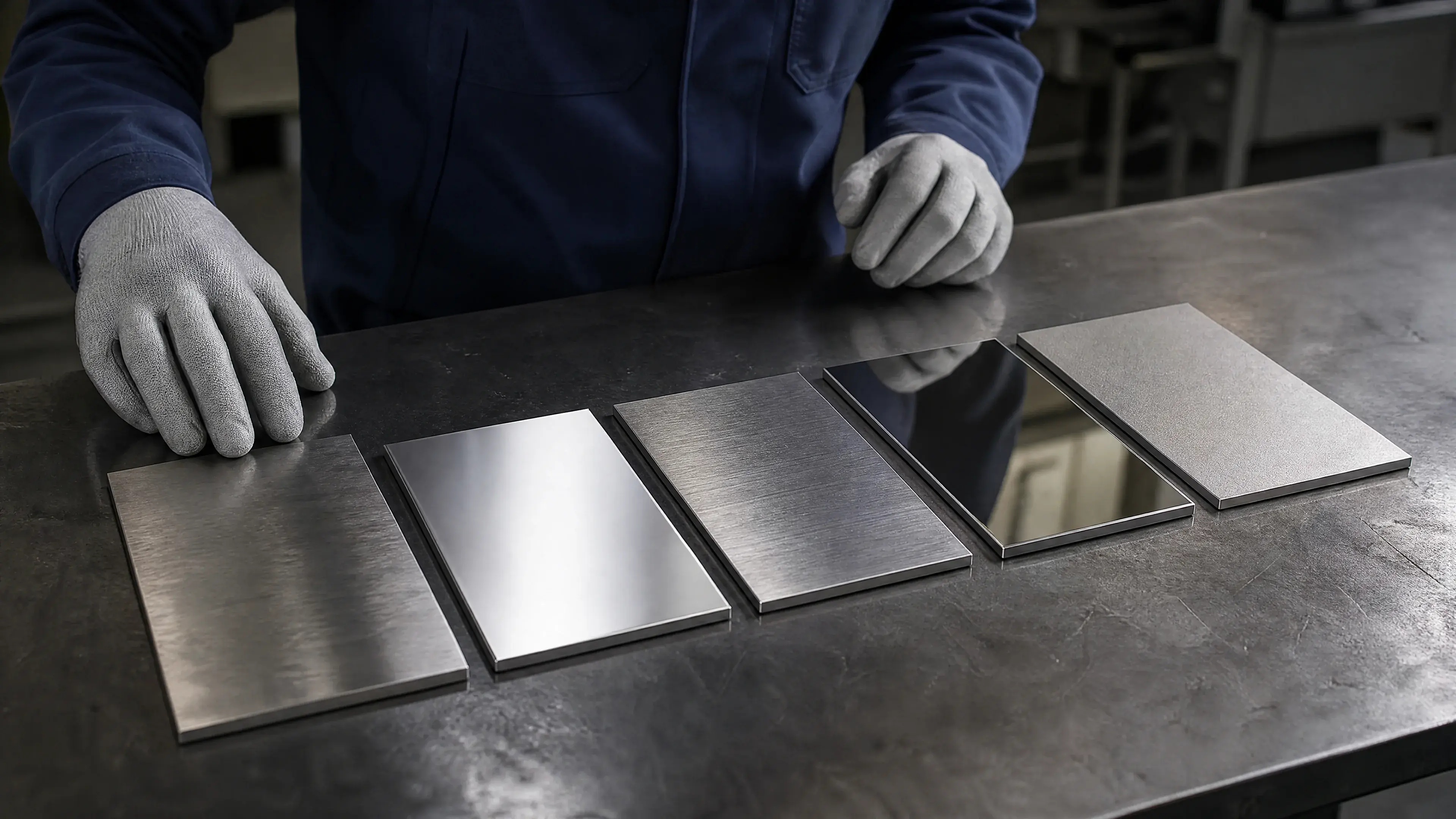
Photography is useful for communication but should not replace a physical master for subtle metallic appearance. Camera exposure, white balance, compression, display calibration, and viewing environment can conceal the disputed difference.
8. Measurement Locations and Sampling
One convenient reading cannot represent a large, nonuniform fabrication. Divide the part into zones based on process and risk:
- broad parent-metal flats;
- weld seams and heat-affected transitions;
- formed corners and bends;
- edges and cutouts;
- repaired areas;
- internal product-contact surfaces;
- sealing or sliding bands;
- coated or masked boundaries.
For each zone, state the number of traces, trace orientation, excluded edge distance if relevant, cleaning condition, and whether every reading or a defined statistic must comply. Preserve individual results. An average can hide one failed weld or scratch-sensitive location.
Instrument method also matters. Peer-reviewed studies comparing stylus and confocal instruments report method-dependent results and uncertainty, so methods should not be treated as automatically interchangeable [6][11]. If supplier and buyer use different technologies, run a correlation study on representative production surfaces before a dispute. A calibration artefact alone may not capture optical reflectivity, steep slopes, deep valleys, or directional texture of the actual part.
9. Uncertainty and Acceptance Rules
Every result has uncertainty contributions from the instrument, reference artefact, calibration, repeatability, resolution, environmental conditions, surface heterogeneity, alignment, operator choices, filtering, and data processing. ISO/IEC 17025:2017 is the official competence standard for testing and calibration laboratories [12]. Accreditation to a scope is valuable, but the report must still describe the method and result relevant to the part.
The contract should answer:
- Is the numerical limit absolute, or is a guard band applied?
- Is conformity declared only when the result plus expanded uncertainty remains within the limit?
- What coverage factor or confidence convention accompanies the stated uncertainty?
- How are indeterminate near-limit results handled?
- Who may authorize retest, additional sampling, rework, or concession?
For example, a reported Ra of 0.79 µm against a maximum 0.80 µm is not self-explanatory if expanded uncertainty is 0.10 µm. This example is illustrative, not a recommended universal rule. The correct rule is the one agreed before measurement and appropriate to the consequence of false acceptance or false rejection [5][7].
10. Substrate, Geometry, and Manufacturing Boundaries
A drawing requirement must be physically compatible with the part. Thin sheet may distort under aggressive grinding. Large mirror panels may meet Ra yet fail reflected-image quality because of waviness. Tight bores may be unreachable by a conventional stylus or polishing tool. Edges remove faster during electropolishing. Weld roots, undercut, pores, and misalignment cannot be cured by asking for a lower mean roughness.
Different stainless families and conditions polish differently. Austenitic, ferritic, duplex, martensitic, precipitation-hardening, and free-machining grades vary in hardness, work hardening, inclusions, and phase structure. A process qualified on annealed 304 sheet is not automatically transferable to cold-worked 316 tube or duplex plate. Require representative first articles.
11. Procurement and Approval Workflow
- Identify the function and consequence of failure. Separate appearance, cleanability, sealing, coating, fatigue, wear, and corrosion needs.
- Choose one standards system. Establish ISO or ASME conventions and editions. Record any controlled exception.
- Zone the part. Mark critical, visible, product-contact, welded, repaired, and inaccessible surfaces.
- Select the measurand. Choose only parameters or tests connected to function.
- Define the operator and direction. Include filters, evaluation length, instrument method, locations, and data treatment.
- Add independent controls. Specify defects, appearance, cleanliness, passive condition, or coating requirements separately.
- Create the representative sample. Use production material and the full fabrication route.
- Correlate inspection. Compare supplier and buyer results, methods, software settings, and uncertainty.
- Approve first article. Verify drawing, PO, sample, process record, dimensions, texture, and visual condition together.
- Freeze revision and change control. Tool, abrasive, chemistry, subcontractor, material, software, or instrument changes may require requalification.
- Accept final condition. Inspect after finishing, cleaning, marking, protective film, packing trial, and any permitted repair.
12. Better Alternatives to a Weak Surface Note
Replace “180 grit all over” with a zoned texture requirement plus an approved process and visual master.
Replace “mirror finish” with a controlled sample, optical acceptance method where needed, waviness/flatness requirement, and defect criteria.
Replace “Ra 0.8” with parameter, units, standard edition, operator, direction, locations, sampling, uncertainty, and decision rule.
Replace “pickled and passivated” with separate starting-condition, oxide-removal, contamination-removal, rinse, cleanliness, and verification requirements.
Replace a cross-standard “equivalent finish” note with one governing designation and independent functional/appearance acceptance criteria.
Replace a texture proxy with a cleanability, adhesion, leak, friction, corrosion, or wear test when that performance is the actual design requirement.
13. Application Examples
Architectural panel: control grade, side, grain direction, batch, master sample, viewing geometry, gloss/color variation, flatness, weld repair, protective film, and installation orientation. A roughness number is secondary unless tied to the chosen appearance.
Food-contact vessel: zone all product-contact surfaces and welds; control material, geometry, cracks/pits/crevices, texture operator, inspection direction, cleaning access, and sanitation validation. Do not label the drawing simply “food-grade finish.”
Seal face: define the profile and direction that the seal design requires, plus flatness, waviness, defects, and any functional leakage test. A decorative finish designation is irrelevant.
Electropolished tube: define starting tube condition, weld condition, final dimensions, internal measurement method, locations, final texture, defect limits, cleanliness, and batch record. External shine does not prove internal conformance [9].
Powder-coated stainless enclosure: define substrate finish, contamination control, pretreatment, coating system and thickness, color tolerance, adhesion test, edge and masked zones, cure record, and repair. Do not accept by “smooth finish” alone.
14. Buyer Checklist
- The title block or specification names one standards system and edition.
- Legacy symbols have a documented interpretation rather than assumed modern defaults.
- Required surfaces and exceptions are zoned.
- Parameter, limit, units, filter/operator, evaluation length, and direction are complete.
- Measurement locations, trace count, and reporting rule are defined.
- Supplier and buyer instrument methods are specified or correlated.
- Appearance, texture, process, cleanliness, and defects are separate controls.
- Grain direction is controlled through cutting, bending, welding, and installation.
- The approved sample represents production grade, thickness, geometry, and route.
- Welds, edges, bores, corners, and repairs have feasible acceptance rules.
- Uncertainty and the conformity decision rule are agreed before inspection.
- Product-standard finish designations include their governing edition.
- First article, process changes, deviations, and repairs require traceable approval.
- Final inspection occurs after all fabrication, cleaning, marking, and packaging operations.
15. FAQ
Is the surface-texture symbol enough by itself?
Usually not. It needs the governing system and edition plus complete parameter and operator information. Appearance, defects, cleanliness, and process restrictions may require linked specifications [1][2][4].
Can I write “Ra 0.8” in a general note?
You can, but it is incomplete. Add units, limit type, standard edition, filtering/evaluation conditions, direction, locations, sampling, instrument method, and conformity rule.
Should I specify grit and Ra together?
Only when grit controls a qualified manufacturing route and Ra independently accepts the output. Do not imply a universal conversion.
Can ISO and ASME surface symbols be treated as equivalent?
No blanket equivalence is defensible. Use one system consistently or document an edition-specific translation verified from licensed standards.
What should I do with an old ISO 1302 drawing?
ISO marks ISO 1302:2002 withdrawn [3]. Identify the original edition and historical inspection basis, protect replacement fit and function, and issue a controlled current requirement for new production rather than silently changing interpretation.
Is a physical sample more important than Ra for decorative stainless?
Often yes, because Ra does not control gloss, color, image clarity, waviness, grain length, or local visual defects. Use both when texture also protects a function.
Who decides whether a near-limit result passes?
The contract’s pre-agreed decision rule. It should account for measurement uncertainty and the consequences of false acceptance and false rejection [5][7].
Can a production process name replace final inspection?
No. It may support process control, but tool wear, chemistry, geometry, starting material, and handling can change the output. Inspect the final required characteristics.
Should welds use the same requirement as parent metal?
Only if that is functional and achievable. Welds often need explicit controls for completion, blend, heat tint, pits, undercut, geometry, texture, and cleanliness.
References
- ISO. ISO 21920-2:2021, Geometrical product specifications (GPS)—Surface texture: Profile—Part 2: Terms, definitions and surface texture parameters. Edition 1, published December 2021. Official record: https://www.iso.org/standard/72226.html. Access note: official ISO catalogue metadata reviewed; protected standard text was not accessed or reproduced.
- ISO. ISO 21920-3:2021, Geometrical product specifications (GPS)—Surface texture: Profile—Part 3: Specification operators. Edition 1, published December 2021. Official record: https://www.iso.org/standard/72228.html. Access note: official ISO catalogue metadata reviewed; protected standard text was not accessed or reproduced.
- ISO. ISO 1302:2002, Geometrical Product Specifications (GPS)—Indication of surface texture in technical product documentation. Edition 4, withdrawn. Official record: https://www.iso.org/standard/28089.html. Access note: official ISO catalogue metadata and withdrawn status reviewed; protected standard text was not accessed or reproduced.
- ASME. ASME Y14.36-2018 (R2024), Surface Texture Symbols. Official record: https://www.asme.org/codes-standards/find-codes-standards/y14-36-surface-texture-symbols/2018. Access note: official ASME catalogue record reviewed; protected standard text was not accessed or reproduced.
- Joint Committee for Guides in Metrology. JCGM 100:2008, Evaluation of measurement data—Guide to the expression of uncertainty in measurement. Official BIPM text: https://www.bipm.org/documents/20126/2071204/JCGM_100_2008_E.pdf. Access note: official BIPM full text reviewed.
- Mínguez-Martínez, A., et al. “Results of a Surface Roughness Comparison between Stylus Instruments and Confocal Microscopes.” Materials 15, no. 16 (2022): 5495. https://doi.org/10.3390/ma15165495. Access note: open-access full text reviewed through PubMed Central (PMC9410296).
- Taylor, B. N., and C. E. Kuyatt. NIST Technical Note 1297: Guidelines for Evaluating and Expressing the Uncertainty of NIST Measurement Results. 1994 edition. Official record: https://www.nist.gov/pml/nist-technical-note-1297. Access note: official NIST full text reviewed.
- Bartkowiak, T., et al. “Discrimination of Surface Topographies Created by Two-Stage Process by Means of Multiscale Analysis.” Materials 14, no. 22 (2021): 7044. https://doi.org/10.3390/ma14227044. Access note: open-access full text reviewed through PubMed Central (PMC8624860).
- Lochyński, P., et al. “Electropolishing of Stainless Steel in Laboratory and Industrial Scale.” Metals 9, no. 8 (2019): 854. https://doi.org/10.3390/met9080854. Access note: open-access full text reviewed.
- Kozior, T., and J. Bochnia. “The Influence of Printing Orientation on Surface Texture Parameters in Powder Bed Fusion Technology with 316L Steel.” Micromachines 11, no. 7 (2020): 639. https://doi.org/10.3390/mi11070639. Access note: open-access full text reviewed.
- García, J. C., et al. “Some Considerations about the Use of Contact and Confocal Microscopy Methods in Surface Texture Measurement.” Materials 11, no. 8 (2018): 1484. https://doi.org/10.3390/ma11081484. Access note: open-access full text reviewed.
- ISO. ISO/IEC 17025:2017, General requirements for the competence of testing and calibration laboratories. Edition 3. Official record: https://www.iso.org/standard/66912.html. Access note: official ISO catalogue metadata reviewed; protected standard text was not accessed or reproduced.
Continue the specification
Related surface-finish guides


Specify before production
Need a finish quoted against a drawing or control sample?
Send the material grade, product form, finish requirement, inspection method and quantity. We will identify the unresolved specification points before quoting.
Discuss the requirement