Stainless steel surface engineering
Mirror Polishing Stainless Steel: Define the Reflected Image, Not Just the Finish Name
In this guide
TL;DR
Mirror polishing is a sequence of surface preparation and progressively finer mechanical finishing intended to reduce visible line structure and produce a clear reflected image. “Mirror” is not one universal technical grade. A part may be bright yet show...

1. What mirror polishing is
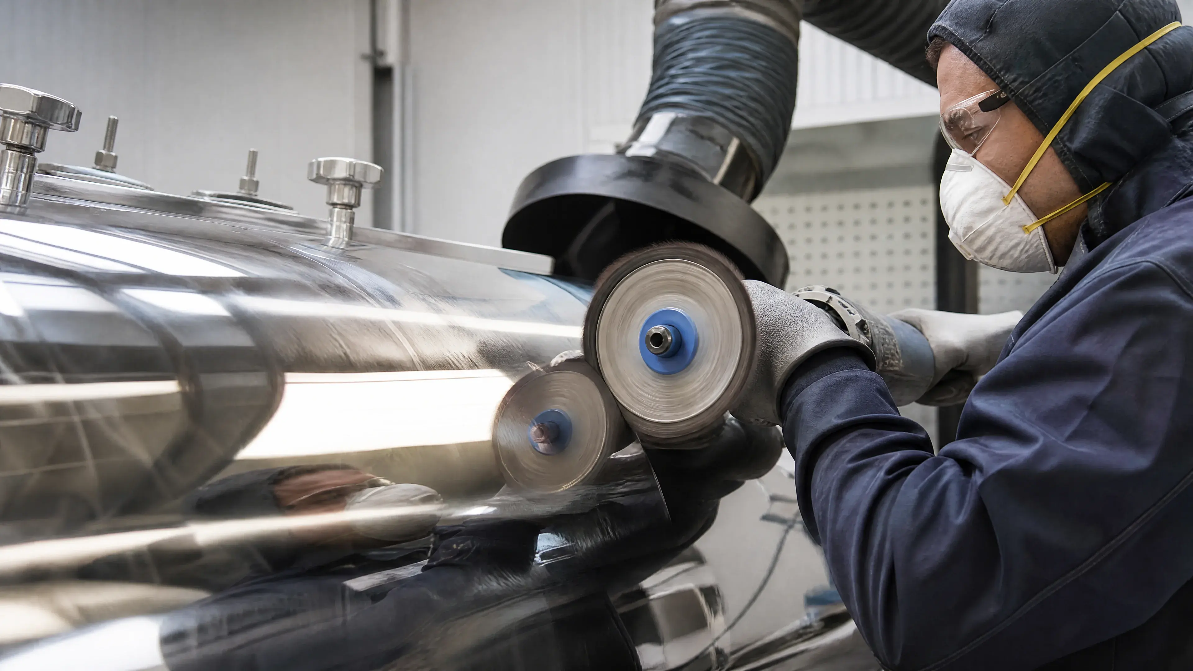
Mirror polishing is a result-oriented mechanical finishing route. The surface is first made sufficiently flat and free of deep defects, then processed through progressively finer abrasive stages. Later polishing or buffing stages reduce the visible line pattern and increase reflected-image clarity. The exact tools may include belts, wheels, compounds, pads, or other qualified media, but the finish should be purchased by its demonstrated result rather than by an assumed universal recipe.
Starting condition controls how much preparation is required. Cold-rolled sheet with shallow marks presents a different task from hot-rolled plate, a welded tank, a machined block, or a formed panel. Deep scratches, pits, scale, weld mismatch, distortion, and prior coarse grinding cannot be reliably hidden by a final buff. They must be removed or bounded earlier, with enough dimensional allowance to preserve the part.
The sequence is cumulative. A coarse-stage scratch that survives into a later stage may remain as a long bright line in the finished reflection. Changing to a finer abrasive does not automatically erase deeper damage, especially if the operator shortens preparation time or works around geometry. Inspection between stages is therefore part of process control, not merely cosmetic housekeeping.
Terms such as mirror, mirror-polished, No.8, 2P, super mirror, and optical mirror appear in commercial and project language. They should not be assumed to be equivalent. The official records reviewed here establish the product scope of ASTM A480/A480M and EN 10088-2, but their protected finish tables were not inspected [9][10]. A contract must cite the controlled standard text it actually uses and add project-specific optical acceptance rather than rely on an informal label conversion.
2. Brightness is not the complete mirror result
A bright surface returns a large amount of light. A useful mirror also preserves information in the reflected image. Those are related but different properties. A surface can have strong highlights while softening fine detail, bending straight lines, or showing a cloudy halo. Another surface can show high local clarity but reveal broad distortion across a large panel.
At least five attributes may need independent control:
Reflected-image clarity concerns how sharply the surface reproduces a target. A resolution pattern, straight-line grid, or agreed real object can expose blur and distortion.
Gloss is an instrumented light-reflection measurement at a declared geometry. It does not by itself show whether reflected lines remain straight or whether fine haze surrounds a highlight.
Haze and residual texture describe fine scattering, faint directional lines, compound marks, and local cloudiness. These can be highly visible under point lighting even when a broad gloss value passes.
Flatness and waviness govern large-scale image distortion. A short roughness trace may miss a panel-scale ripple introduced by rolling, welding, grinding pressure, heat, or support conditions.
Local defects include scratches, pits, digs, dents, edge roll-off, drag marks, compound residue, and discolored zones. An average optical or texture value can hide a defect that is unacceptable in a focal area.
The order should state which attributes matter. A decorative column, a close-view equipment panel, an optical component, and a distant architectural soffit do not need the same inspection. “Mirror” without viewing context forces the parties to discover the target after polishing is complete.
3. The process begins with defect removal and form control
Mirror work is often described as a march toward finer abrasives, but the decisive early question is whether the substrate can support the requested image. Inspect incoming material for pits, laminations, dents, roll marks, weld undercut, misalignment, heat distortion, and thickness or flatness constraints. Decide which defects can be removed, which require repair, and which exceed the material allowance.
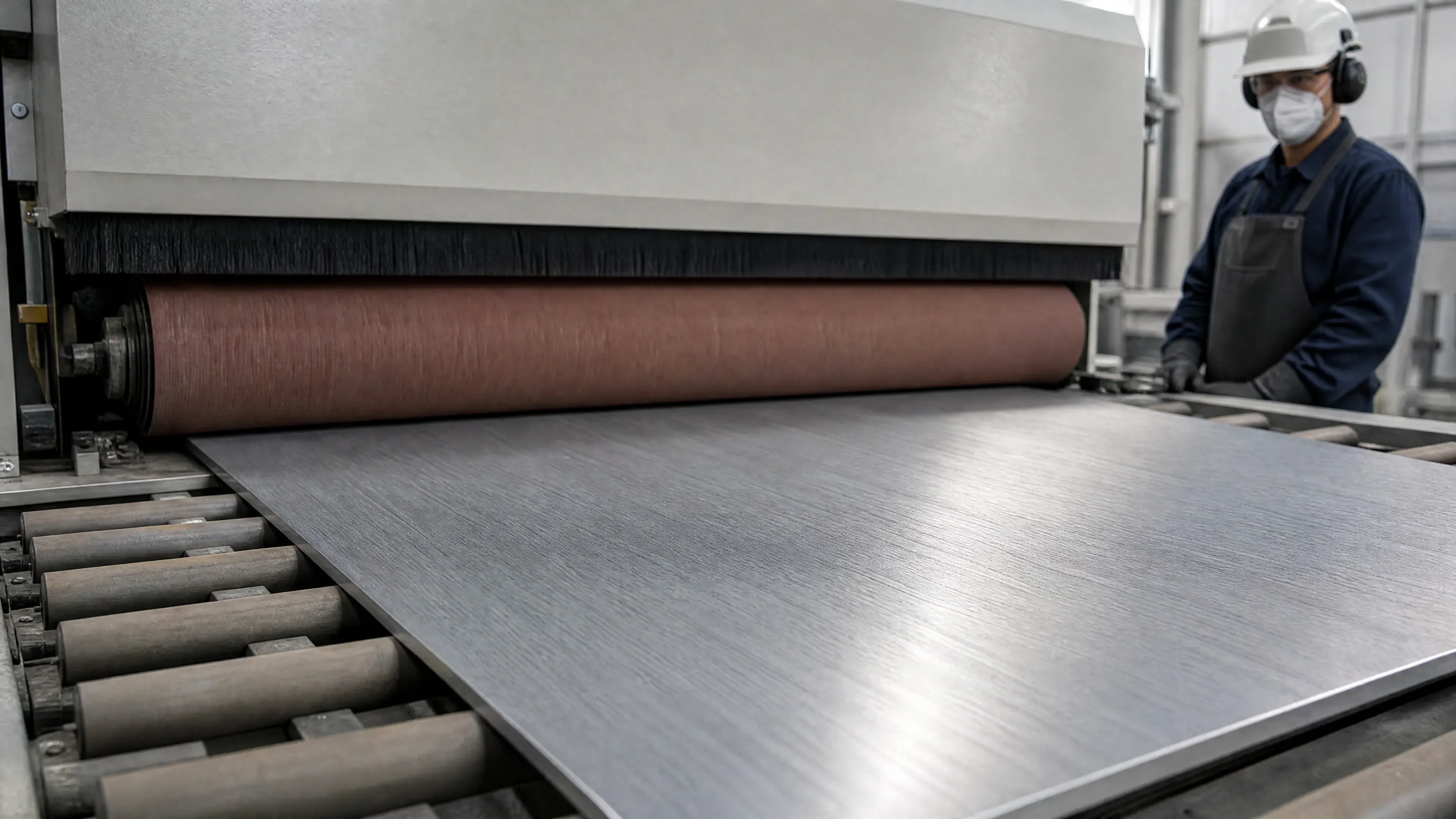
Coarse preparation establishes a continuous surface. On a weld, that may mean bringing weld metal and parent material into an agreed contour without thinning the wall or creating a flat spot. On sheet, it may mean removing transport scratches while preserving panel form. On a machined component, it may mean blending tool marks without rounding a functional edge.
Each subsequent stage should remove the characteristic traces of the previous stage. The finisher needs a controlled change point, clean media, consistent pressure, planned direction, overlap, and adequate inspection. An inspected abstract on flap-wheel finishing of stainless cookware identified multiple grinding variables affecting roughness in its reported case [3]. Because only the abstract was reviewed, it does not support a transferable speed, pressure, abrasive, or pass count. It does support refusing a one-number grit recipe as the complete specification.
Heat management matters. Excessive local pressure can change compound behavior, distort thin sheet, or create a patch with a different appearance. Edges and corners remove material faster than broad faces and are vulnerable to rounding. Feature-specific tooling and stop rules should be qualified before production.
Final polishing can improve reflectivity but cannot correct every long-wavelength error. If the panel is wavy before finishing, polishing may make the distortion more visible by creating a clearer reflected image. Material flatness, fabrication sequence, fixturing, welding, stress, and installed support must therefore be considered alongside the surface process.
4. Roughness, topography, and optical appearance
Surface roughness measurements can be useful for process control or a functional requirement, but no single Ra value defines a mirror. Ra is an average of profile deviations after specified filtering. It does not state scratch direction, defect density, haze, reflected-image clarity, or panel waviness.
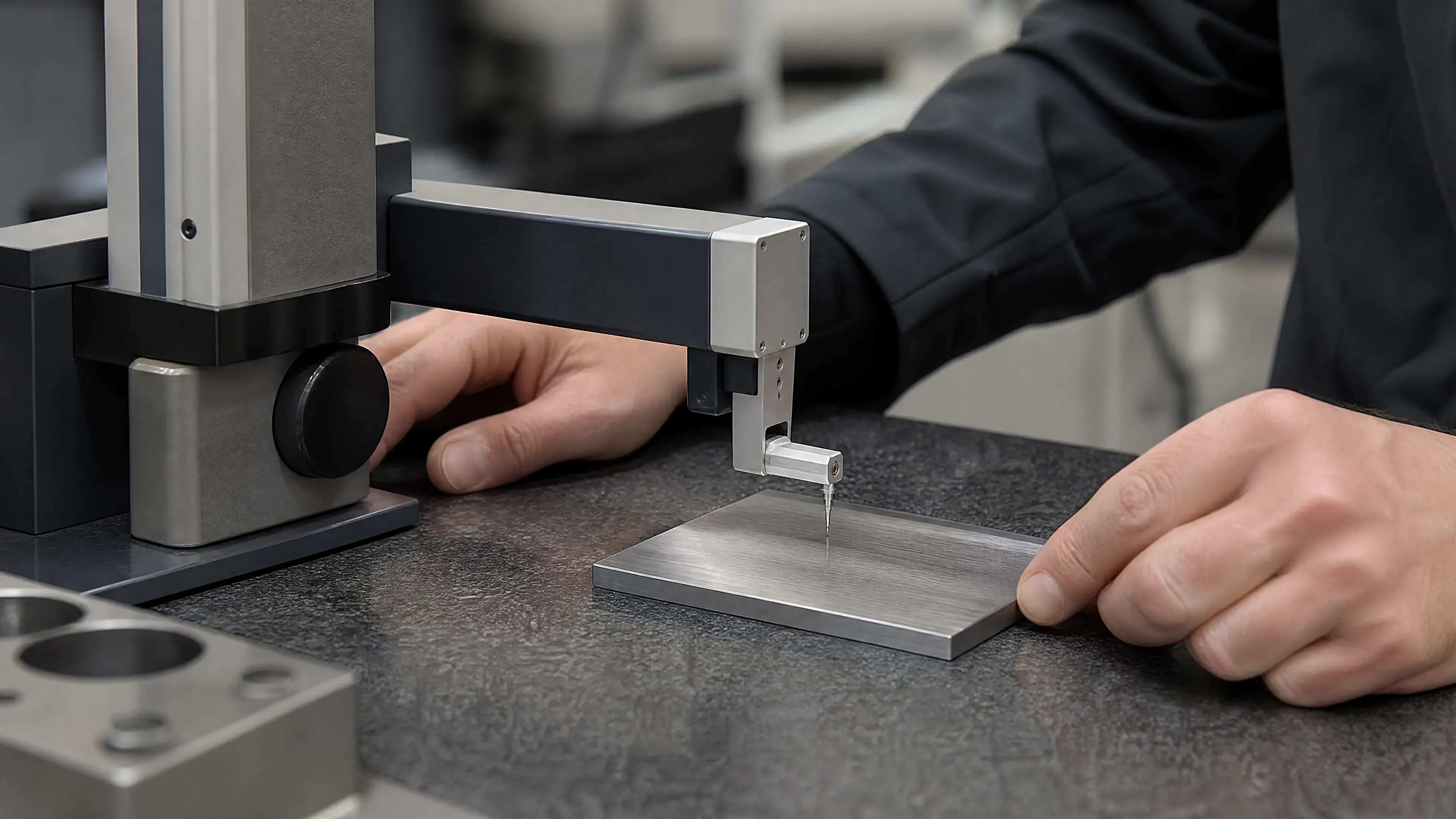
Measurement method must be written. Contact stylus and optical approaches acquire and process topography differently. Peer-reviewed comparisons of stylus and confocal methods show that instrument principle and evaluation choices can affect the reported description [4][5]. These studies do not establish a mirror threshold; they support declaring the method rather than publishing a universal conversion.
Scale also matters. Bartkowiak and co-workers used multiscale analysis to discriminate topographies created by staged processes [6]. That work is relevant to the fact that a polishing sequence leaves information at more than one spatial scale. It does not mean that every mirror order needs multiscale laboratory analysis. It means a buyer should not expect one short-profile average to capture fine haze, residual lines, and broad form simultaneously.
When roughness is specified, include parameter, units, instrument type, filter, cutoff, evaluation length, direction, locations, number of traces, and acceptance statistic. On a nominally non-directional final mirror, traces may still encounter residual process direction. Map scratches and pits separately instead of allowing an average to absorb them.
For optical acceptance, use a documented target and geometry. Define target distance, observer or camera position, illumination, viewing distance, clean state, and controlled zones. A physical reference panel remains valuable because it integrates attributes that a single number can miss. Store and handle the reference carefully so its condition does not drift.
5. Corrosion claims require application-matched evidence
Mechanical polishing removes material and changes topography. It may also alter near-surface deformation, expose inclusions, leave residues, or interact with later cleaning and passivation. None of those facts creates a universal direction of corrosion performance.
Messinese and co-workers compared cold-drawn and ground bars across several stainless alloys and localized-corrosion tests [1]. The full text shows that starting condition, alloy, finishing, and exposure matter together. The specimens were not commercial mirror sheet, so the paper cannot prove that mirror polishing always improves resistance.
Rokosz and co-workers compared defined mechanically polished and electropolished states across different stainless steels and examined electrochemical behavior and passive-layer composition [2]. Their findings depended on material and process conditions. A more reflective electrochemical route did not justify a simple universal performance ranking. The study is valuable because it separates visual smoothness from corrosion evidence, not because it supplies a mirror recipe.
DOI records for a Type 301 roughness and pitting study and for machining or grinding effects on stress-corrosion sensitivity were verified, but no abstract or lawful full text was inspected [7][8]. Their titles identify relevant research questions; no result from them is used in this article. This explicit boundary matters because a title cannot support a claim about direction, mechanism, or magnitude.
For corrosion-sensitive service, name the alloy, fabricated condition, cleaning and contamination controls, exposure, test method, acceptance threshold, and sampling plan. If a passive treatment is required after polishing, specify and verify it separately. A mirror image is visual evidence only.
6. Cleanability and contamination are not optical properties
A highly reflective surface can make visible soil easier to notice, but visibility is not the same as validated cleanability. Microscopic pits, crevices, weld defects, compound residue, embedded foreign material, poor drainage, and inaccessible geometry may remain. The completed component matters more than an isolated flat coupon.
Polishing compounds and media need contamination control. A dirty wheel can transfer material from another alloy or process. Residual compound can lodge in corners, threads, holes, seams, and under attachments. Cleaning should have a defined procedure, rinse or residue requirement where relevant, and final inspection. Do not certify cleanliness by brightness alone.
If product contact, vacuum, laboratory, semiconductor, pharmaceutical, food, or another controlled environment is involved, the project should identify its own material, geometry, residue, particle, cleaning, passivation, packaging, and validation requirements. This article does not assign “hygienic” or “cleanroom” status to a generic mirror finish.
Use separate records: a visual approval for appearance, a cleaning or residue record for cleanliness, a material certificate for alloy identity, and an application-specific qualification for service performance. Combining them into one word creates hidden risk.
7. Bends, welds, corners, lettering, and edges
Geometry changes polishing access and material-removal rate. Broad flat faces can be processed with one tool path; tight inside corners, narrow returns, radii, cutouts, embossed features, and engraved marks may require different tools. Those changes can leave visible transitions even when every zone is individually bright.
Welded mirror assemblies need early qualification. Welding adds heat tint, filler metal, distortion, and a surface contour that must be dressed before fine polishing. A successful flat-sheet sample does not prove an invisible weld on a curved tank or thin door. Build a representative coupon using the actual joint, thickness, weld process, access, and polishing sequence.
Edges are vulnerable to rounding and over-polishing. State which edges must remain sharp within a dimensional limit, which may be eased, and which are appearance-critical. Protect threaded features, sealing lands, engraved data, and fit surfaces. If polishing allowance affects dimensions, put it on the drawing.
Lettering and marks need a sequence decision. Polishing after engraving can soften edges; marking after polishing can discolor or scratch the surface. Approve the complete sequence, including final cleaning and protection, on a representative sample.
Do not promise that local repair will be invisible. A scratch repair can create a brighter patch, a depression, residual directional lines, or a halo under point light. Define permitted repair zones, maximum attempts, blend area, resubmission, and the same optical inspection used for new work.
8. Large panels and image distortion
Large mirrors are a system problem. Product flatness, sheet thickness, residual stress, weld sequence, grinding pressure, heat, support frame, adhesive, fasteners, and installation all affect the reflected image. A coupon can approve microfinish while missing panel-scale distortion.
Use a full-size first article or representative assembly when the reflection extends across a large field. Inspect with straight-line or grid targets at agreed distances. Review both free and installed states if support can change the surface. Mark unacceptable zones and distinguish local scratch criteria from broad optical distortion.
Panel matching also requires source control. Different lots or finishing batches may vary in color, haze, line residue, and form. Map source material, cutting sequence, finish batch, orientation, and installed adjacency. For a multi-panel wall, judge the complete elevation rather than approving each sheet in isolation.
Lighting should represent the intended service. Point sources expose fine haze and buff marks; grazing light exposes waviness; diffuse light can hide both. Define the relevant conditions without inventing an adversarial test that the project never required. The physical reference and first article should be reviewed under the same agreement.
9. Protective film, cleaning, and packaging
Mirror surfaces are easily damaged after acceptance. Specify protective film compatible with the finishing residue, forming or assembly steps, storage duration, temperature, and intended removal. Aged adhesive, trapped particles, or rubbing can create visible patterns. Final inspection must occur after film removal at an agreed stage.
Define cleaning materials and technique. Abrasive pads, dirty cloths, unsuitable chemicals, or dry wiping of particles can scratch a finished face. Use a qualified cleaning method and ensure that the retained reference receives the same clean condition during comparison.
Packaging should prevent face-to-face rubbing, edge impact, vibration, moisture entrapment, and contamination. Use clean interleaving and rigid protection appropriate to part size. Record who owns inspection after unpacking and how transport damage is distinguished from production nonconformance.
10. RFQ and drawing requirements
- Material identity: grade, product form, thickness, dimensions, condition, and traceability.
- Governing documents: exact product standard and edition, plus project-specific mirror requirements.
- Starting surface: mill finish, plate, weld, machining, previous grinding, defects, and dimensional allowance.
- Controlled zones: faces, edges, returns, corners, cutouts, lettering, sealing lands, and hidden functional surfaces.
- Optical reference: approved physical sample or first article, revision, size, target, lighting, distance, angle, and cleanliness.
- Appearance limits: clarity, haze, residual lines, scratches, pits, orange peel, drag marks, waviness, edge roll-off, and transitions.
- Measured requirements: gloss, roughness, color, flatness, or other parameters, each with instrument, settings, locations, sample count, and acceptance rule.
- Fabrication sequence: forming, welding, grinding, polishing, marking, cleaning, passivation if required, and assembly.
- Feature rules: weld contours, bend appearance, corner strategy, edge dimensions, protected features, and accessible tooling assumptions.
- Repair: permitted zones, method, maximum attempts, repeat inspection, and rejection boundary.
- Matching and protection: lot, batch, panel map, first-article size, film, handling, cleaning, storage, and packaging.
- Release records: material certificates, process traveler, first-article approval, raw measurements, defect or repair map, cleaning record, and final signoff.
11. Inspection workflow
Inspect the substrate before polishing. Confirm identity, starting condition, thickness or dimensional allowance, flatness risk, weld condition, and defects. Reject or document features that cannot be removed without violating geometry.
At process qualification, prepare a representative coupon or first article through the complete sequence. Inspect between stages for residual scratches. At final polish, compare the clean surface with the approved reference and target under agreed light. Record any declared roughness, gloss, clarity, color, or form measurements.
During production, preserve part identity and monitor media cleanliness, change points, tool access, heat, repair, and handling. Keep accepted and unaccepted parts segregated. Do not let unrecorded local buffing become the default response to every defect.
At final release, inspect the complete controlled area after cleaning and film removal at the agreed stage. Review large assemblies in their matching order. Repeat affected checks after repair. Link acceptance to material lot, drawing and sample revision, process record, measurements, defect map, cleaning, and packaging.
12. Common failures and buyer checklist
“Mirror polish to 600 grit.” A nominal abrasive does not define the complete sequence or final optical result [3].
“Mirror, Ra as standard.” A roughness number is not image clarity, haze, or panel form [4][5][6].
“No visible defects.” Visibility needs light, distance, angle, controlled zones, and defect boundaries.
“All welds invisible.” Demonstrate the actual joint and geometry before volume production.
“Mirror means corrosion proof or hygienic.” Visual reflectivity does not establish service performance [1][2].
Before release, confirm that the specification names the material and starting condition; defines the reflected-image target; separates optical, texture, form, and service requirements; addresses edges, welds, bends, marks, and repair; qualifies a representative sample; controls matching and film; and requires records that connect the accepted part to its process and inspection.
References
- Messinese, E., Casanova, L., Paterlini, L., Capelli, F., Bolzoni, F., Ormellese, M., & Brenna, A. “A Comprehensive Investigation on the Effects of Surface Finishing on the Resistance of Stainless Steel to Localized Corrosion.” Metals, 12 (2022), 1751. https://doi.org/10.3390/met12101751. Access note: DOI metadata matched and official open full-text PDF was inspected; the tested bars and environments are not a production qualification for mirror sheet.
- Rokosz, K., Solecki, G., Mori, G., Fluch, R., Kapp, M., & Lahtinen, J. “Effect of Polishing on Electrochemical Behavior and Passive Layer Composition of Different Stainless Steels.” Materials, 13 (2020), 3402. https://doi.org/10.3390/ma13153402. Access note: DOI metadata matched and peer-reviewed open full text was inspected; conclusions remain bounded to the reported alloys, polishing routes, electrolytes, and tests.
- Somgumnerd, J., Saetang, V., & Prombanpong, S. “Effects of Flap Wheel Grinding Parameters on Surface Roughness for Stainless Steel.” Applied Mechanics and Materials (2014). https://doi.org/10.4028/www.scientific.net/AMM.548-549.506. Access note: DOI metadata and publisher-deposited abstract were inspected; use is limited to its multi-variable stainless cookware case, with no numerical recipe generalized.
- Mínguez-Martínez, A., et al. “Results of a Surface Roughness Comparison between Stylus Instruments and Confocal Microscopes.” Materials, 15 (2022), 5495. https://doi.org/10.3390/ma15165495. Access note: DOI metadata and peer-reviewed open full text were inspected; use is limited to measurement-method considerations, not a mirror threshold.
- García, J. C., et al. “Some Considerations about the Use of Contact and Confocal Microscopy Methods in Surface Texture Measurement.” Materials, 11 (2018), 1484. https://doi.org/10.3390/ma11081484. Access note: DOI metadata and peer-reviewed open full text were inspected; no universal conversion between methods is asserted.
- Bartkowiak, T., et al. “Discrimination of Surface Topographies Created by Two-Stage Process by Means of Multiscale Analysis.” Materials, 14 (2021), 7044. https://doi.org/10.3390/ma14227044. Access note: DOI metadata and peer-reviewed open full text were inspected; use is limited to general multiscale topography principles.
- Hong, T., & Nagumo, M. “Effect of Surface Roughness on Early Stages of Pitting Corrosion of Type 301 Stainless Steel.” Corrosion Science (1997). https://doi.org/10.1016/S0010-938X(97)00072-3. Access note: DOI metadata matched title, authors, journal, and year; no abstract or full text was inspected, so no result from the paper is used.
- Turnbull, A., Mingard, K., Lord, J. D., Roebuck, B., Tice, D. R., Mottershead, K. J., Fairweather, N. D., & Bradbury, A. K. “Sensitivity of Stress Corrosion Cracking of Stainless Steel to Surface Machining and Grinding Procedure.” Corrosion Science (2011). https://doi.org/10.1016/j.corsci.2011.06.020. Access note: DOI metadata matched title, authors, journal, and year; no abstract or full text was inspected, and no result is attributed to it.
- ASTM International. ASTM A480/A480M-25b, Standard Specification for General Requirements for Flat-Rolled Stainless and Heat-Resisting Steel Plate, Sheet, and Strip. https://store.astm.org/a0480_a0480m-25b.html. Access note: official catalog record and public scope inspected; protected finish tables and normative clauses were not accessed or reproduced.
- Estonian Centre for Standardisation and Accreditation. EVS-EN 10088-2:2024, Stainless steels—Part 2: Technical delivery conditions for sheet/plate and strip of corrosion resistant steels for general purposes. https://www.evs.ee/en/evs-en-10088-2-2024. Access note: official national-standards catalog record inspected; normative text was not accessed, so no No.8-to-2P equivalence is asserted.
Continue the specification
Related surface-finish guides

Specify before production
Need a finish quoted against a drawing or control sample?
Send the material grade, product form, finish requirement, inspection method and quantity. We will identify the unresolved specification points before quoting.
Discuss the requirement