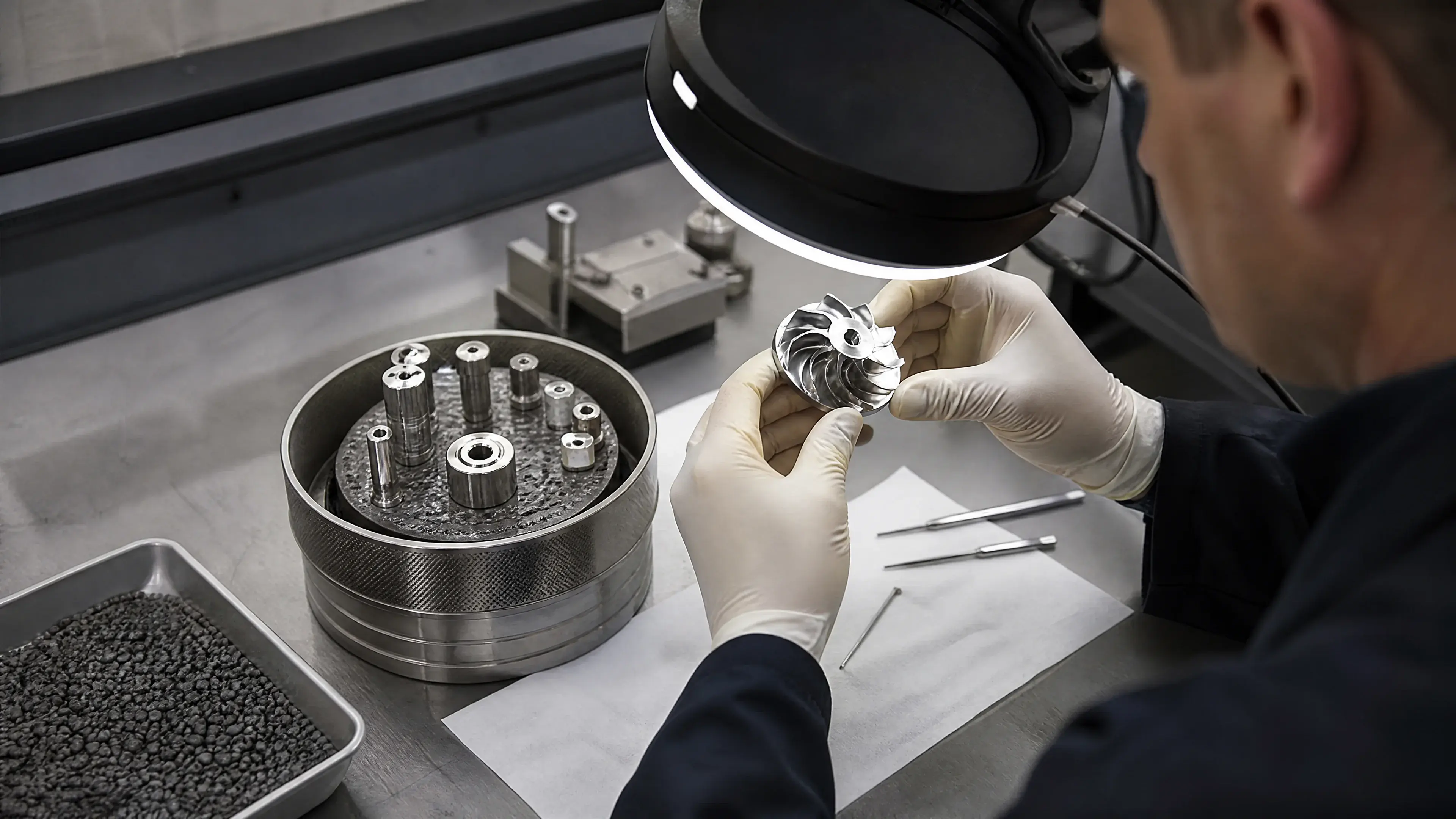
Stainless steel surface engineering
Magnetic Polishing of Stainless Steel: A Practical Guide to Magnetic Abrasive Finishing
In this guide
TL;DR
“Magnetic polishing” usually refers to magnetic abrasive finishing (MAF): a magnetic field holds and controls a flexible mass of ferromagnetic carrier particles and hard abrasive near a stainless-steel surface while relative motion produces micro-cutting,...
1. What “magnetic polishing” means
Magnetic abrasive finishing uses a magnetic field to organize and retain a finishing medium in the machining gap. The medium commonly combines magnetically responsive particles with hard abrasive grains, either as separate particles, mechanically mixed material, or composite magnetic abrasive. Under the field, the particles form a flexible brush-like structure between a magnetic pole and the work surface. Relative motion makes the abrasive act on surface asperities [4][5][6].
The process is better described as field-controlled abrasive finishing than as polishing by magnetic attraction. Material is removed through small-scale mechanical interactions. Magnetic force helps establish normal load and keeps the medium in the intended zone; rotation, translation, vibration, or reciprocation supplies tangential motion. Both are necessary for effective cutting and smoothing [4][5][6].
Several process families sit under the broad label. External MAF acts on a face or outside diameter. Internal MAF places the abrasive in a tube while magnets outside create the finishing zone. Some systems rotate the workpiece, others rotate or translate the magnetic poles, and some combine motions. Electrolytic magnetic abrasive finishing adds anodic dissolution to mechanical abrasive action and must be treated as a separate hybrid process with electrical and chemical controls [2][5][6].
The distinction is important in an RFQ. “Magnetic polish” does not state whether the process is purely mechanical or electrochemical, whether loose or bonded media are used, or which surfaces receive the magnetic brush. The processor should name the process variant and demonstrate it on representative geometry before the result is converted into a drawing requirement [2][3][5][6].
2. How magnetic abrasive finishing works
Formation of the flexible magnetic brush
When ferromagnetic particles enter a nonuniform magnetic field, they align along field lines and are attracted toward regions of stronger field. In the working gap they create a semi-bonded, deformable tool. Hard abrasive grains carried within or among those particles contact the stainless surface. The field distribution and gradient determine where the brush is concentrated and how strongly it presses against the work [4].
Marczak and Zawora modeled magnetic-field distribution in a finishing station and related it to effects on AISI 304L stainless steel [4]. Their work supports a practical rule: quoting only magnet type or nominal field strength is not enough. Pole shape, gap, workpiece position, and the magnetic circuit determine the local field that actually controls the abrasive.
For austenitic stainless steel, which may be weakly magnetic in its supplied condition, the workpiece itself does not need to function as a conventional magnetic tool. The external field can still control magnetically responsive media across a gap. Process designs may also use a magnetic or metastable-austenitic tool element to shape the finishing zone; Yamaguchi, Kang, and Hashimoto investigated such a tool concept [1]. That research should not be generalized into a claim that every stainless part or work-hardened region behaves identically.
Micro-cutting, ploughing, and burnishing
As the brush moves relative to the surface, abrasive grains encounter peaks. Depending on grain geometry, load, and speed, they cut small chips, plough material sideways, or burnish the surface. Early passes often act on the tallest asperities; later improvement can slow as the profile becomes smoother or the abrasive becomes loaded or worn. The balance between removal and deformation is specific to the medium and process window [4][5][6].
Increasing force or time is not automatically beneficial. Too little engagement produces negligible change; too much can generate scratches, excessive edge rounding, embedded debris, heating, or dimensional loss. Coarse abrasive can remove topography faster but may leave its own texture, while fine abrasive may be inefficient against deep starting marks. A staged sequence can be appropriate, but it must be qualified for the material and finish target [4][5][6].
Internal tube finishing
For internal MAF, abrasive media are placed inside a tube and an external magnetic assembly forms the brush through the wall. Relative rotation and axial motion sweep the finishing zone along the bore. Yamaguchi, Shinmura, and Ikeda studied internal finishing of austenitic stainless capillary tubes, and Yamaguchi, Shinmura, and Sekine examined uniform finishing of bent SUS304 tubing [2][3]. These studies establish feasibility while also showing why wall thickness, curvature, pole access, media transport, and path strategy belong in process qualification.
A straight coupon does not represent a bend. In a curved tube, the gap between external pole and internal surface changes around the circumference, and media can redistribute along the path. Ends, transitions, and the intrados and extrados of a bend may receive different action. Uniformity needs measurements at defined axial and circumferential locations, not one reading at an accessible tube end [2][3].
Electrolytic hybrid finishing
Electrolytic MAF superimposes anodic dissolution on magnetic abrasive action. Sun and Zou studied an electrolytic magnetic abrasive system for SUS304 plane finishing, and Xing, Zou, and Tojo investigated a pulse-voltage variant [5][6]. Mechanical action can disturb or remove surface films while electrochemical dissolution contributes material removal; the combined result depends on both sets of variables.
This hybrid is not interchangeable with dry or lubricated mechanical MAF. It adds electrolyte chemistry, electrode geometry, voltage or current waveform, electrical contact, rinsing, residue, and safety controls. A buyer who permits only mechanical finishing should say so. A buyer considering the hybrid should specify chemical restrictions, material-removal allowance, post-process cleaning, and the required passive or corrosion condition [5][6].
3. Variables that control the result
Magnetic field and working gap
The finishing force depends on field strength and spatial gradient at the abrasive, not merely on a magnet’s nameplate rating. Pole material, pole-tip geometry, yoke, magnet spacing, workpiece position, wall thickness, and working gap all affect the field. A small position change can alter force and brush shape, especially near edges or curved surfaces [4].
The gap also contains the active media. Too narrow a gap can compact the brush, restrict circulation, or cause aggressive contact; too wide a gap can weaken control and allow media loss. Part runout or tube ovality can therefore create periodic finish variation. Production fixtures should locate the surface repeatably and, for rotating parts, control concentricity [4].
Abrasive and magnetic medium
Media variables include carrier material, abrasive type, grain size and shape, mixture ratio, composite-particle construction, quantity, and condition after reuse. The carrier must respond to the magnetic field; the abrasive must cut the stainless surface without introducing unacceptable contamination or texture. Lubricant or carrier fluid affects friction, media movement, debris removal, and heat [4][5][6].
Media life should be controlled because grain fracture, loading with removed metal, lubricant change, and loss of the fine fraction can shift performance. A production traveler should identify the approved media family and replacement rule. If cleanliness or elemental contamination is critical, the buyer should require residue analysis or a qualified cleaning step rather than assume that all media are chemically benign [4][5][6].
Speed, feed, stroke, and time
Relative speed sets the frequency and severity of abrasive interactions. Axial feed or pole traverse determines dwell along the surface; stroke length and overlap affect banding. Treatment time determines cumulative exposure but can reach diminishing returns as peaks are removed. The open full-text studies show that combined-process parameters interact rather than operate independently [4][5][6].
A useful procedure therefore defines a controlled combination of speed, feed, stroke, number of passes, path, and media refresh. Scaling from a small specimen to a long tube or large panel requires preserving the relevant contact and dwell conditions, not simply multiplying time by area [2][3][4].
Starting surface and material condition
MAF is most credible when the defect scale matches the abrasive action demonstrated in a representative trial. Deep scratches, weld undercut, pits, heavy scale, laminations, and large support scars must not be assumed removable without showing that dimensions remain acceptable [2][3][4].
Alloy grade and metallurgical state matter. Published results for SUS304, AISI 304L, or the studied austenitic capillary material demonstrate those cases, not every stainless family [2][3][4]. Cold work can change austenitic stainless magnetic response; heat treatment and inclusions can change mechanical finishing behavior. Mixed weld metal and parent plate may finish differently.
Geometry, stiffness, and access
Thin walls and delicate features can deflect under magnetic and abrasive forces. Edges may round faster than broad faces, while recesses outside the effective field remain unfinished. A magnetic pole that can follow an external tube may not reach a manifold junction or closed cavity. The RFQ should supply section thickness, access limits, prohibited contact zones, and allowable edge-radius change [2][3].
For internal work, the processor needs bore size, wall thickness, length, bends, branches, end access, and cleanliness constraints. Media recovery is a design requirement: loose particles left in a process line can be more harmful than the original roughness. A verified flush, inspection, and recovery method should be part of release [2][3].
4. Performance and limits
Roughness reduction
MAF can reduce profile roughness by acting abrasively on the surface. The magnitude depends on starting texture, abrasive, load, kinematics, and measurement location. The cited studies report improvements under their own experimental conditions, but those values should not be copied into an unrelated RFQ [2][3][4][5][6].
Surface roughness is not a single self-defining number. ISO 21920-2 defines profile surface-texture terms and parameters, while ISO 21920-3 addresses specification operators [7][8]. A drawing should identify the parameter, filter and evaluation conditions, direction, location, and applicable standard edition. Ra alone can hide isolated scratches or pits and does not describe waviness or edge condition.
Deburring and edge condition
If deburring is part of the requirement, the qualification must define the starting burr, protected dimensions, and permitted edge change. A large attached burr, weld spatter, or folded machining chip should not be assigned to MAF without representative evidence that adjacent dimensions remain acceptable [4].
Edge rounding is both a possible result and a risk. A controlled radius may improve handling or flow, but an uncontrolled radius can change an orifice, sealing land, cutting edge, or thread. Inspect critical edge geometry separately from face roughness, and state whether the requirement applies before or after finishing [4].
Appearance and lay
MAF can brighten a surface as fine asperities decrease, but it does not necessarily erase the previous directional lay or macroscopic waviness. Tool paths may create helical, circumferential, or banded patterns. Visual acceptance should use fixed lighting and a representative sample, while engineering acceptance should use measured topography [4].
An apparently bright tube end does not prove uniform internal finish along its length. Bores require measurement at meaningful positions, which may involve witness coupons, sectioned qualification pieces, replica methods, or suitable internal metrology. The method and sampling plan should be agreed before production [2][3].
Cleanliness and corrosion condition
Mechanical MAF does not itself constitute chemical passivation. It can leave lubricant, abrasive, ferromagnetic carrier, and stainless wear debris. Subsequent cleaning must remove these residues, and the purchase order should state whether pickling, passivation, electropolishing, or a validated cleaning cycle follows [5][6].
Corrosion behavior can be influenced by roughness, embedded material, residual stress, and surface chemistry, but a lower Ra does not prove corrosion resistance in a specified environment. If corrosion performance matters, select an alloy- and service-relevant test and keep its acceptance criterion separate from roughness. The electrolytic hybrid may also alter passive-surface chemistry, requiring its own verification [5][6].
Dimensional and process limits
MAF removes material and is unsuitable as an assumed zero-removal cosmetic process. Critical bores, wall thicknesses, slots, edges, sealing faces, and threads need an allowance and post-process inspection. Mass loss on a coupon can monitor a run but cannot prove local removal on a complex part [4][5][6].
The method also depends on a usable magnetic circuit and relative motion. Very large panels, deeply shielded cavities, thick-walled vessels, complex branch passages, and parts with no access for media recovery may be poor candidates. A feasibility trial should answer access, uniformity, cycle time, cleaning, and metrology before production pricing is fixed [2][3][4].
5. Stainless grades and part compatibility
Research supports MAF on several austenitic stainless geometries using SUS304/AISI 304L and austenitic capillary tubing [2][3][4][5][6]. This evidence makes those cases reasonable qualification starting points, not automatically approved combinations. Material certification and the actual cold-work or heat-treatment condition should be available.
Grades with a different magnetic response from the studied austenitic materials can change force distribution and fixturing behavior. Ferritic, martensitic, duplex, and precipitation-hardening grades therefore require dedicated trials rather than parameter transfer from 304 [4].
Welded tubing and assemblies need review of bead profile, heat tint, filler, distortion, and access. MAF may smooth accessible bead or bore regions, but it cannot repair lack of fusion, cracks, porosity, undercut, or geometric mismatch. Weld acceptance must occur before finish acceptance, and any chemical cleanup after MAF needs a qualified route [2][3].
Coated, plated, adhesively bonded, or multi-material assemblies are generally higher risk. Abrasive action can damage a coating edge; magnetic particles can lodge in polymers or joints; magnets can attract ferrous inserts unexpectedly. Process parts before final assembly where practical, or validate masking, media containment, and cleaning on the complete assembly [4].
6. Inspection and acceptance
Record material grade, heat or batch where required, drawing revision, starting finish, machine or station ID, pole and fixture setup, gap, media identity and condition, lubricant, motion parameters, time, lot, and inspection results. For a hybrid electrolytic route, also record the approved electrolyte and electrical process controls [5][6].
Visual inspection should identify scratches, banding, over-rounded edges, untreated zones, retained scale, discoloration, and media residue. Use magnification appropriate to the defect limit. A visual pass does not replace profile measurement, internal coverage evidence, or dimensional inspection [4].
Profile roughness measurements must follow the drawing’s specified standard and locations [7][8]. Report individual readings and direction, not only a batch average. For a bent tube, sample the straight sections, bend regions, and relevant circumferential positions. For a plane, include edges and center if field distribution could vary [3][4].
Dimensional checks should focus on bores, wall thickness, edges, threads, sealing features, and small openings. When destructive access is required, the first-article plan can use an extra representative part or a process coupon with equivalent geometry. Coupons should be shown to correlate with the production surface before they become the sole routine control [2][3][4].
Cleanliness release should confirm removal of magnetic particles, abrasive, lubricant, and metallic debris. A magnet near the outlet may help process recovery but is not, by itself, a validated cleanliness test. The buyer must define the relevant inspection, flush, particle, extractable, or analytical method and its acceptance threshold [2][3][5][6].
7. Practical workflow
- Define the function. Confirm whether the target is roughness, small-burr removal, edge radius, appearance, internal cleanability, or preparation for a later process.
- Review material and geometry. Record grade, condition, wall thickness, bore, bends, branches, access, stiffness, critical dimensions, welds, and prohibited zones.
- Inspect the starting surface. Map deep defects, scale, burrs, weld issues, and baseline roughness at the future acceptance locations.
- Select and qualify the process variant. Choose external or internal MAF, motion scheme, pole and fixture, media, lubricant, and whether an electrolytic hybrid is permitted [2][5][6].
- Prepare and fixture. Clean shielding soils, remove major defects, establish the working gap, locate the part, and provide media containment and recovery.
- Run controlled finishing. Apply the approved magnetic setup, speed, feed, path, time, and media condition; monitor runout, temperature, and abnormal media loss [4][5][6].
- Recover media and clean. Flush or wash all treated zones, verify drainage, and prevent recontamination.
- Apply downstream surface treatment if specified. Perform qualified passivation, electropolishing, or other cleaning only when required by the contract.
- Inspect and release. Measure roughness and dimensions at defined locations, inspect edge and visual condition, verify cleanliness, and link results to the lot.
This workflow makes the first article especially important. The first article should represent production wall thickness, bends, starting texture, loading, and access. A short flat coupon can qualify media behavior, but it cannot prove uniformity in a long bent bore [2][3].
8. Alternatives and neighboring processes
Rigid grinding, honing, and mechanical polishing provide direct cutting action and can be considered when a field-controlled flexible brush cannot remove the defect scale efficiently. They require their own access, lay, dimensional, and cleanliness qualification; MAF is not automatically more accurate.
Abrasive flow machining uses pressure-driven abrasive media rather than a magnetic brush and can be evaluated for passages with different access. Its pressure, flow path, edge change, and media recovery require separate qualification from the internal MAF routes studied here [2][3].
Electropolishing removes stainless electrochemically and can micro-level a passive surface without loose magnetic carrier. It requires electrical contact, electrolyte access, and current distribution. The hybrid MAF/electrolytic process deliberately combines the mechanisms and should not be specified as either one alone [5][6].
Drag, centrifugal, and vibratory finishing are batch media processes that may suit selected external parts. Protected faces, internal access, part-to-part contact, and media lodging need separate evaluation rather than inference from MAF results.
Chemical pickling and passivation address surface chemistry rather than the controlled abrasive leveling described here. They may follow MAF when the contract requires a chemical surface condition; neither operation should be treated as the automatic substitute for the other [5][6].
9. Typical applications
Austenitic stainless capillary tubing
Small bores are difficult to reach with a rigid tool. Internal MAF can place media inside while external poles control the active zone. The qualification must address bore size, wall thickness, length, end effects, media recovery, and inspection access. Yamaguchi and co-workers studied this process class directly [2].
Bent stainless tubing
Bent tubing adds changing pole gap and circumferential geometry. A controlled traverse can finish the bore, but measurements must demonstrate uniformity through the bend rather than only at straight ends. Research on SUS304 bent tubing provides a technical foundation for this application boundary [3].
Precision flat or gently curved components
304/304L plates and components can be finished under a moving magnetic pole or rotating brush. Field uniformity, path overlap, edge shielding, and workpiece flatness control the result. Finite-element field analysis and experimental studies show why station geometry belongs in process development [4][5][6].
Small machined parts with micro-burrs
MAF may be evaluated for fine burrs and tool marks on accessible zones without a rigid polishing wheel. It is credible only when the starting burr, protected edges, dimensional allowance, and cleanliness are defined and verified on representative parts.
10. RFQ checklist
- Stainless grade, heat treatment or cold-work condition, product form, and traceability requirement.
- Drawing revision, quantity, lot definition, and post-finish dimensional condition.
- Process scope: mechanical MAF or explicitly approved electrolytic hybrid; external face, outside diameter, bore, bend, or designated zones.
- Starting finish, baseline roughness map, machining lay, weld condition, oxide, burr size, and known defects.
- Geometry data: bore, wall thickness, length, bends, branches, edge radii, runout, stiffness, and media access/recovery points.
- Surfaces to protect, allowed fixture or pole access, and prohibited ferromagnetic contamination.
- Roughness parameter and ISO edition, filter/evaluation conditions, direction, locations, sampling, and individual-reading limits [7][8].
- Material-removal, bore-size, wall-thickness, edge-radius, thread, and sealing-face limits.
- Appearance definition with lighting and approved reference sample where relevant.
- Media and lubricant restrictions, residue and particle limits, cleaning method, and packaging.
- Required downstream passivation, electropolishing, corrosion verification, or surface chemistry.
- First-article plan, production-equivalent fixture and path, certificate wording, records, and failed-lot disposition.
11. Frequently asked questions
Can magnetic polishing finish nonmagnetic austenitic stainless steel?
Yes, established MAF research includes austenitic SUS304/AISI 304L and austenitic capillary tubing. The field controls magnetically responsive abrasive media, so the workpiece does not have to behave like a conventional permanent magnet. Its magnetic response and wall geometry can still affect the field and must be considered [2][3][4].
Does the process polish without touching the part?
No. The magnetic field controls the abrasive brush, but abrasive grains contact the surface and remove material. The process is compliant rather than contact-free. It can scratch, round edges, or change dimensions if poorly controlled [4][5][6].
Is magnetic polishing a substitute for electropolishing or passivation?
No. Mechanical MAF changes topography through abrasive action. Electropolishing uses anodic dissolution, and chemical passivation targets a clean passive surface. A hybrid MAF process can include electrolytic action, but it then needs both electrochemical and abrasive controls [5][6].
Can one roughness reading at a tube end qualify the whole bore?
No. Field, gap, media distribution, and dwell can change along the tube and around a bend. The qualification should define axial and circumferential measurement locations or a validated representative method, especially for long or bent tubing [2][3].
References
- Yamaguchi, H., Kang, J., & Hashimoto, F. “Metastable austenitic stainless steel tool for magnetic abrasive finishing.” CIRP Annals (2011). https://doi.org/10.1016/j.cirp.2011.03.119. Access note: DOI metadata verified; no abstract or lawful full text was inspected, so the source is used only to identify the studied tool concept stated in its title.
- Yamaguchi, H., Shinmura, T., & Ikeda, R. “Study of Internal Finishing of Austenitic Stainless Steel Capillary Tubes by Magnetic Abrasive Finishing.” Journal of Manufacturing Science and Engineering (2006). https://doi.org/10.1115/1.2738957. Access note: DOI metadata and indexed abstract verified; no unreviewed numerical result is reproduced.
- Yamaguchi, H., Shinmura, T., & Sekine, M. “Uniform Internal Finishing of SUS304 Stainless Steel Bent Tube Using a Magnetic Abrasive Finishing Process.” Journal of Manufacturing Science and Engineering (2004). https://doi.org/10.1115/1.1951786. Access note: DOI metadata and indexed abstract verified; use is limited to the published scope and qualitative process boundary.
- Marczak, M., & Zawora, J. “Finite Element Analysis of the Magnetic Field Distribution in a Magnetic Abrasive Finishing Station and its Impact on the Effects of Finishing Stainless Steel AISI 304L.” Metals, 11 (2021), 194. https://doi.org/10.3390/met11020194. Access note: open-access full text reviewed.
- Sun, X., & Zou, Y. “Study on Electrolytic Magnetic Abrasive Finishing for Finishing Stainless Steel SUS304 Plane with a Special Compound Machining Tool.” Journal of Manufacturing and Materials Processing, 2 (2018), 41. https://doi.org/10.3390/jmmp2030041. Access note: open-access full text reviewed.
- Xing, B., Zou, Y., & Tojo, M. “Study on Magnetic Abrasive Finishing Combined with Electrolytic Process–Precision Surface Finishing for SUS 304 Stainless Steel Using Pulse Voltage.” Journal of Manufacturing and Materials Processing, 6 (2022), 14. https://doi.org/10.3390/jmmp6010014. Access note: open-access full text reviewed.
- International Organization for Standardization. ISO 21920-2:2021, Geometrical product specifications (GPS) — Surface texture: Profile — Part 2: Terms, definitions and surface texture parameters, Edition 1, published 2021-12. https://www.iso.org/standard/72226.html. Access note: title, edition, publication date, and active “Published” status verified in the official ISO catalogue; protected standard text was not accessed or reproduced.
- International Organization for Standardization. ISO 21920-3:2021, Geometrical product specifications (GPS) — Surface texture: Profile — Part 3: Specification operators, Edition 1, published 2021-12. https://www.iso.org/standard/72228.html. Access note: title, edition, publication date, and active “Published” status verified in the official ISO catalogue; protected standard text was not accessed or reproduced.
Continue the specification
Related surface-finish guides
Specify before production
Need a finish quoted against a drawing or control sample?
Send the material grade, product form, finish requirement, inspection method and quantity. We will identify the unresolved specification points before quoting.
Discuss the requirement