In short: press-brake bending forms sheet metal by pressing a punch into a V-die to fold a straight line to a target angle. Two things decide whether the finished part is right. First, springback: once the punch lifts, the elastic part of the deformation recovers and the bend opens up slightly, so the brake must over-bend to land on the wanted angle — and the springback is larger along the rolling direction than across it, and grows as the bend angle increases.[1] Second, the neutral axis — the layer inside the bend that is neither stretched nor compressed. Because metal resists compression better than tension, that neutral layer shifts inward toward the inside of the bend, which is captured by the K-factor (≈ 0.3–0.5) and is what makes the bend allowance / flat-pattern (developed length) calculation correct.[2] Get the K-factor and springback right and the blank cuts to size and the flange lands on angle; get them wrong and every part is short or off-angle. For curved shells and cylinders rather than sharp folds, the part goes to plate rolling instead.
What Press Brake Bending Is
Press-brake bending is a forming process: a sheet-metal blank is laid across a V-shaped die in the lower bed of the machine, and a punch mounted on the descending ram presses the sheet down into the die, folding it along a straight line to a programmed angle. On a CNC press brake the ram stroke, the back-gauge position (which sets where the bend lands along the part), and the bending sequence are all numerically controlled, so the same complex profile can be reproduced part after part.
It is the natural next step after flat-sheet laser cutting: a profiled blank comes off the cutter, and the brake turns it into a three-dimensional part — a flange, a U-channel, a box, an enclosure — by a series of straight folds. At steelhui it is the primary route for angular forming of stainless and steel sheet, complementing plate rolling, which produces continuous curvature (cylinders and cones) rather than discrete folds.
The deceptively simple act of folding hides the two problems this guide is built around. The metal does not stay where the punch leaves it — it springs back elastically when the load is removed — and the blank must be cut to a length that accounts for how the material stretches and shifts through the bend. Master both and bending is fast, accurate, and repeatable; ignore either and the parts come out short or off-angle.
V-Die Bending Geometry: Die Opening, Tonnage, and the Minimum Flange
The geometry of the fold is set by the V-die opening — the width of the V slot the punch presses into. The die opening governs three things at once: the force (tonnage) needed, the inside bend radius that forms, and the minimum flange (the shortest leg the brake can fold without the sheet slipping into the die). As a rule of thumb the inside radius scales with the die opening, and the smallest flange the part can carry is tied to it too — which is why tooling is chosen for the material and thickness, not the other way around.
There are two distinct ways to bottom the punch into the die, and the choice changes everything downstream.
Air bending — the flexible default
In air bending the punch presses the sheet only part-way into the V; the sheet contacts the die at three lines (the two die shoulders and the punch nose) and never touches the bottom of the V. The bend angle is set purely by how far the ram descends — push deeper for a sharper angle, less deep for an open one — so one set of tooling can produce a whole range of angles. That flexibility is why air bending is the everyday method on a CNC brake. The cost is that air bending is more sensitive to springback: because the sheet is not forced against the die, the elastic recovery on unloading is larger and must be compensated by ram depth.
Bottoming — coining the angle into the die
In bottoming the punch presses the sheet hard against the walls of the V, so the die angle dictates the part angle. Forcing the material against the tooling sets the bend more positively and reduces springback, giving tighter, more repeatable angles — at the price of much higher tonnage and a die ground for the specific angle wanted. Bottoming (and the more extreme coining) trades the flexibility of air bending for consistency where the angle tolerance is tight.
Rule of thumb: air bend for flexibility and lower force (set the angle by ram depth); bottom the bend when you need the die to hold a tight, repeatable angle and can afford the tonnage.
Springback: Why the Angle Opens — and How It Is Compensated
Springback is the single most important phenomenon in bending. When the punch deforms the sheet, the deformation has two parts: a plastic part that stays, and an elastic part that is stored like a spring. The moment the punch lifts and the load is removed, the elastic part recovers — the bend relaxes and the angle opens up slightly toward flat. The finished angle is therefore always a little more open than the angle the punch held at the bottom of the stroke.
Two relationships matter for predicting it. First, springback depends on direction relative to rolling: the springback factor is higher along the rolling direction than across (transverse to) it, a consequence of the anisotropy the sheet picks up when it is rolled. Second, springback grows as the bend angle increases — sharper, larger-angle bends store and release more elastic strain. Both effects are documented experimentally for V-die air bending, where springback is, at root, simply the elastic recovery of the bent section on unloading.[1]
The fix is over-bending: deliberately bend past the target so that, once the elastic part springs back, the part settles on the angle wanted. On a CNC brake this is done by setting the ram a little deeper than the nominal angle would require — the springback compensation built into the bend program. The right amount depends on the material, its temper, the thickness, the die opening, and the bend angle, so the practical workflow is to bend a test piece, measure the actual angle, and dial the compensation in before running the batch. Get the compensation right once and every part repeats; guess at it and the whole batch comes out a degree or two open.
Springback is elastic recovery, not error — it is always present. The skill is predicting it (material, direction, angle, thickness, die) and over-bending by exactly the right amount.
Neutral Axis, K-Factor, and Developed Length
To cut the flat blank to the right size you have to know how the metal behaves through the thickness of the bend. On the outside of the bend the material is stretched (tension); on the inside it is compressed. Somewhere between the two is a layer that is neither stretched nor compressed — the neutral axis (neutral layer). The length of the part is preserved along that neutral layer, so it is the line you measure to work out how much flat material a bend consumes.[2]
Crucially, the neutral axis does not sit at the mid-thickness. Because metal resists compression better than it resists tension, the neutral layer shifts inward, toward the inside (compressed) face of the bend — and it moves further inward as the bend gets tighter. This inward shift of the strain-neutral layer is the physical basis of both springback behaviour and the flat-pattern calculation, and it is exactly what analytical bending models capture when they let the neutral radius move with the bend radius.[2][3]
The position of the neutral axis is expressed as the K-factor — the ratio of the distance from the inside face to the neutral layer, divided by the material thickness. Because the neutral layer sits inside the mid-plane, the K-factor is less than 0.5; in practice it falls in the range of about 0.3 to 0.5 for sheet metal, depending on material, thickness, and bend radius.[2] A K-factor of 0.5 would mean the neutral layer at mid-thickness; the lower the value, the further inward it has shifted.
From the K-factor you compute the bend allowance — the arc length of the neutral axis through the bend — and from that the developed (flat) length: the total length the blank must be cut to so the finished, folded part hits its dimensions. This is the foundation of blanking size: cut the blank from a wrong developed length and every formed part is the wrong size, no matter how perfectly the angle is set. The flat pattern is therefore worked out from the neutral-axis arc length before the blank is even cut.
Minimum Inside Bend Radius
There is a limit to how tightly a sheet can be folded. As the inside bend radius gets smaller, the outer fiber of the bend has to stretch more and more; once that stretch exceeds the material’s limiting strain, the outer surface cracks. The minimum inside bend radius is the tightest radius the material will take before that happens, and it is usually quoted as a multiple of the sheet thickness.
The governing factor is the material’s ductility. A soft, ductile sheet can be folded to a small radius; a harder, less ductile, or higher-strength material needs a more generous radius to avoid splitting the outer fiber — which is why the minimum bend radius is set by the material, not chosen freely. Analytical models show the same physics from the inside out: the strain-neutral radius moves inward as the bend radius shrinks, and the minimum bend radius is limited by the material’s ductility and reduction-of-area capacity.[3] Bend tighter than that limit and the part cracks; the only fixes are a larger radius, a softer temper, or aligning the bend across the rolling direction.
Minimum bend radius is a material property expressed in thicknesses. Stainless and aluminium tempers differ markedly — see how grade choice changes the bend below.
Precision, Tolerance & Bend Sequence
A finished bent part has to be right in two senses: the angle of each fold and the position of each fold along the part. CNC control of the back gauge holds the position to a tight band, while the angle accuracy comes down to how well springback is compensated and how repeatable the material is from sheet to sheet.
On parts with several bends, the bend sequence matters as much as any single fold. Each completed bend turns the blank into a more three-dimensional shape, and a later bend can drive a previously formed flange into the machine, the tooling, or the ram — an interference (collision) that makes the part impossible to form in that order. The sequence is planned so that every bend stays clear of the tooling and so the part can still be located against the back gauge at each step; the right order is part of programming the job, not an afterthought.
| Max thickness | 12 mm |
| Max length | 4000 mm |
The specification figures above are the single source of truth for this cell. Achievable angle and dimensional tolerance depend on material, thickness, tooling, and the springback compensation dialled in for the job.
Materials & Thickness Range
The press brake forms the flat-sheet materials steelhui works in — principally stainless steel and carbon / mild steel, and aluminium alloys where called for. The same fold behaves differently in each: a soft, ductile temper folds to a tight radius with modest tonnage, while a high-strength or work-hardened grade needs a larger radius and more force, and springs back more.
| Max thickness | 12 mm |
| Max length | 4000 mm |
Two material traits dominate bending. Strength and temper set the tonnage and the springback — stronger, harder material both resists the bend and recovers more on unloading, so it needs more force and more over-bend. Ductility sets the minimum bend radius — a less ductile grade must be folded to a more generous radius to keep the outer fiber below its cracking strain. Because both springback and minimum radius are also tied to the rolling direction, laying the bend line across the rolling direction (rather than along it) gives a tighter achievable radius and more predictable angle. Within the thickness envelope shown above, stainless and carbon-steel sheet are the materials this cell is built around.
Equipment at steelhui
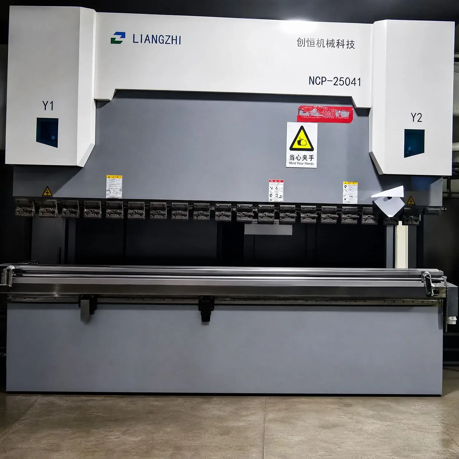
Bending runs on an Accurpress CNC hydraulic press brake. CNC control of the ram stroke sets the bend angle (and the springback over-bend), while the powered back gauge positions the blank so each fold lands where the program puts it. Exact bending length and maximum thickness are listed in the specification table.
| Max thickness | 12 mm |
| Max length | 4000 mm |
In the fabrication flow the brake sits between cutting and welding: a profiled blank is cut on the laser, formed to shape on the brake, and the folded part passes downstream to assembly and welding. The sequence below traces a part from flat pattern to a measured, on-angle bend.
Applications
Press-brake bending turns flat blanks into the three-dimensional sheet-metal parts that make up almost every fabricated assembly — wherever a straight fold, a flange, or a box shape is needed in stainless or steel sheet.
Enclosures, cabinets & chassis
Boxes, cabinets, and equipment chassis folded from a single cut blank into a U or wrap-around form — the bend sequence planned so each fold clears the tooling and the panels meet square for welding. The clean cut edge off the laser means the folded seams fit with no rework.
Brackets & structural angles
Mounting brackets, gussets, and structural angles where a precise, repeatable bend angle carries a load or sets an alignment — exactly the case where springback compensation and a sound minimum bend radius decide whether the part fits.
Flanges & formed edges
Stiffening flanges, lips, and hemmed or folded edges on panels and covers — short formed legs that need the right minimum flange for the die and a clean, crack-free outer radius in the chosen stainless grade.
Sheet-metal parts for assembly
General fabricated sheet-metal components — trays, frames, ducting transitions, and panels — that feed downstream welding and assembly, where the flat pattern must be cut from the correct developed length so every folded part lands on size.
- Improving Prediction of Springback in Sheet Metal Forming Using Multilayer Perceptron-Based Genetic Algorithm. Materials (MDPI), 2020. V-die air-bending springback factor: higher along the rolling direction than transverse, and it grows with bend angle; springback = elastic recovery. ncbi.nlm.nih.gov/pmc/articles/PMC7412272
- Unusual Spreading of Strain Neutral Layer in AZ31 Magnesium Alloy Sheet during Bending. Materials (MDPI), 2022. The neutral layer is the layer neither stretched nor compressed in bending; since metals resist compression better than tension the neutral layer shifts inward — the basis of springback and developed-length (K-factor) calculations. pmc.ncbi.nlm.nih.gov/articles/PMC9787686
- Mechanical Modeling of Tube Bending Considering Elastoplastic Evolution of Tube Cross-Section. Materials (MDPI), 2022. Analytical model: the strain-neutral-layer radius shifts inward as the bend radius shrinks; the minimum bend radius is limited by the material's ductility and reduction of area. pmc.ncbi.nlm.nih.gov/articles/PMC9181969